Aerospace Injection Molding & Custom Mold Making
KTM builds injection molds and supplies molded parts for non-flight-critical aerospace covers, brackets, housings and interior trim. We review the features that affect acceptance: sink on visible PC surfaces, warpage across mounting points, undercut release and resin-specific processing. Choose an export mold for your facility or finished parts supplied through KTM.
PC cosmetic housings and PEEK component experience, with tooling matched to the specified resin grade
Gate, cooling and ejection design reviewed around appearance requirements, assembly datums and critical dimensions
Founder-led tooling decisions, with more than 20 years of mold engineering experience
DFM, trial samples and dimensional reports; Moldflow analysis scoped to filling and warpage risks
Aerospace Part Requirements That Shape the Mold
A cabin cover may be rejected for a visible sink mark; a bracket may fail assembly because its mounting points move after molding. Before cutting steel, we review the drawing revision, resin grade, cosmetic zones and inspection datums. These requirements guide the gate, cooling and release strategy for your aerospace injection mold.

Sink Marks on PC Cosmetic Covers
Ribs, bosses and abrupt wall transitions can leave sink marks on a visible PC face. We review thickness ratios, gate access and local cooling before tooling. Appearance limits are agreed through drawings, texture specifications or reference samples, then checked during trials under the specified viewing conditions.
Warpage on Long, Thin-Wall Structures
Long covers and slender brackets can bow as cooling and shrinkage vary across the part. We review flow direction, wall distribution and datum locations, using simulation where appropriate. Trial inspection then checks mounting features and mating surfaces so tool corrections address assembly fit, not isolated dimensions.
Undercuts, Texture and Weld-Line Placement
Lifters and sliders must release internal features without dragging across a textured show face. We review draft, shutoffs, ejection marks and gate positions together. Predicted weld lines are checked against cosmetic zones and loaded features, then evaluated on trial parts using the agreed appearance and functional criteria.
Mark visible faces, keep-out areas for gates and ejectors, and critical assembly dimensions on your drawing. These details make the DFM review specific to your part.
Concerned about sink marks, warpage or undercut release? Send the drawing revision and mark your critical surfaces for a preliminary tooling review. Initial reply within one working day.
Request a Tooling ReviewWhere Molded Plastics Fit an Aerospace Design
For suitable non-flight-critical covers, brackets and trim, injection molding can combine weight reduction with integrated features. The benefit depends on the specified loads, temperature, fluids and qualification requirements; changing from metal to polymer requires a design review.
Lightweighting
Evaluate a lighter cover or bracket against stiffness, mounting loads and service conditions before replacing a metal component with a molded polymer design.
Part Consolidation
Combine compatible clips, ribs and mounting bosses within one housing, while checking tool access, wall transitions and the assembly sequence before design approval.
Repeatable Volume
Use approved samples, defined critical dimensions and recorded molding conditions to control recurring orders of cabin covers, equipment housings and mounting bracket components.
Thick-Section Options
Review gas assist for suitable handles or ribbed components where hollow sections may reduce material use and sink, subject to geometry and trials.
Our Aerospace Injection Molding Processes
Aerospace housings, trim and brackets need a process matched to their fastening, sealing, surface and size requirements. These six capabilities cover tooling systems and molding routes. KTM builds the tooling and uses in-house production or established partners as appropriate; the quotation identifies the proposed route and inspection scope.
Insert Molding
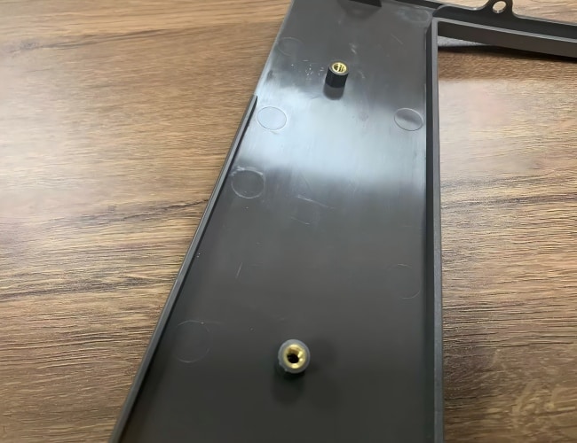
For aerospace housings and mounting brackets, molded-in inserts provide threaded attachment points. We review insert location, surrounding walls, resin flow and retention geometry. Torque and pull-out requirements should be specified so trials can evaluate the fastening interface before production approval.
/insert-molding/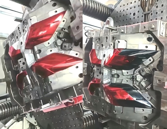
Two-Shot (2K) Molding
Two-shot molding combines compatible rigid and soft materials for enclosure seals or cabin trim. We review substrate geometry, material bonding and shutoff surfaces before selecting dedicated partner equipment. Sealing performance must be evaluated against the specified application and acceptance criteria.
/2k-two-shot-injection-molding/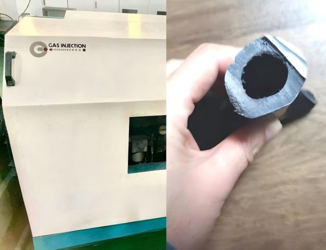
Gas-Assist Molding
For suitable handles and thick ribbed components, gas assist forms hollow sections that can reduce resin use and surface sink. We review gas paths, wall transitions and entry locations, then evaluate the trial parts against appearance, weight and stiffness requirements.
/gas-assisted-injection-molding/
Hot Runner Molds
Hot runner systems feed resin directly to aerospace housing or bracket cavities, reducing cold runner waste. We review gate vestige, cavity balance and resin residence time when selecting the system. Temperature control and maintenance access are considered during mold design.
/hot-runner-mold/
Overmolding
Overmolding adds a second material to a preformed housing or trim substrate, for features such as grips or seals. We review adhesion, mechanical retention and substrate support to control flash and distortion. Material compatibility and service conditions guide trial evaluation.
/overmolding-services/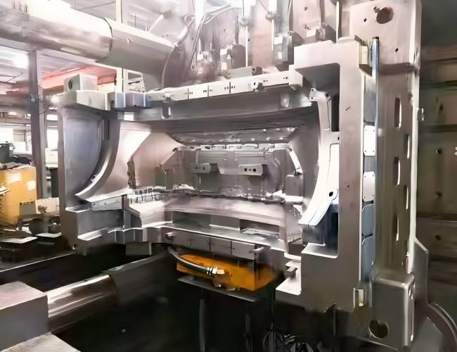
Large Part Injection Molding
Large aerospace covers need suitable mold space, shot capacity and clamp force. We review flow length, gate placement, cooling and ejection alongside press selection. Partner capacity supports projects beyond our machine range, with the production route defined during quotation review.
/large-part-injection-molding/Aerospace Plastics & Mold Steel Selection
Specify the resin grade and filler content, not only the polymer family. PC appearance, PEEK shrinkage and filled-material abrasion create different tooling demands. We review your temperature, fluid exposure, load and documentation requirements before confirming the processing route, mold steel and surface specification.
Resin options to review against your specification
Mold steels and surface requirements
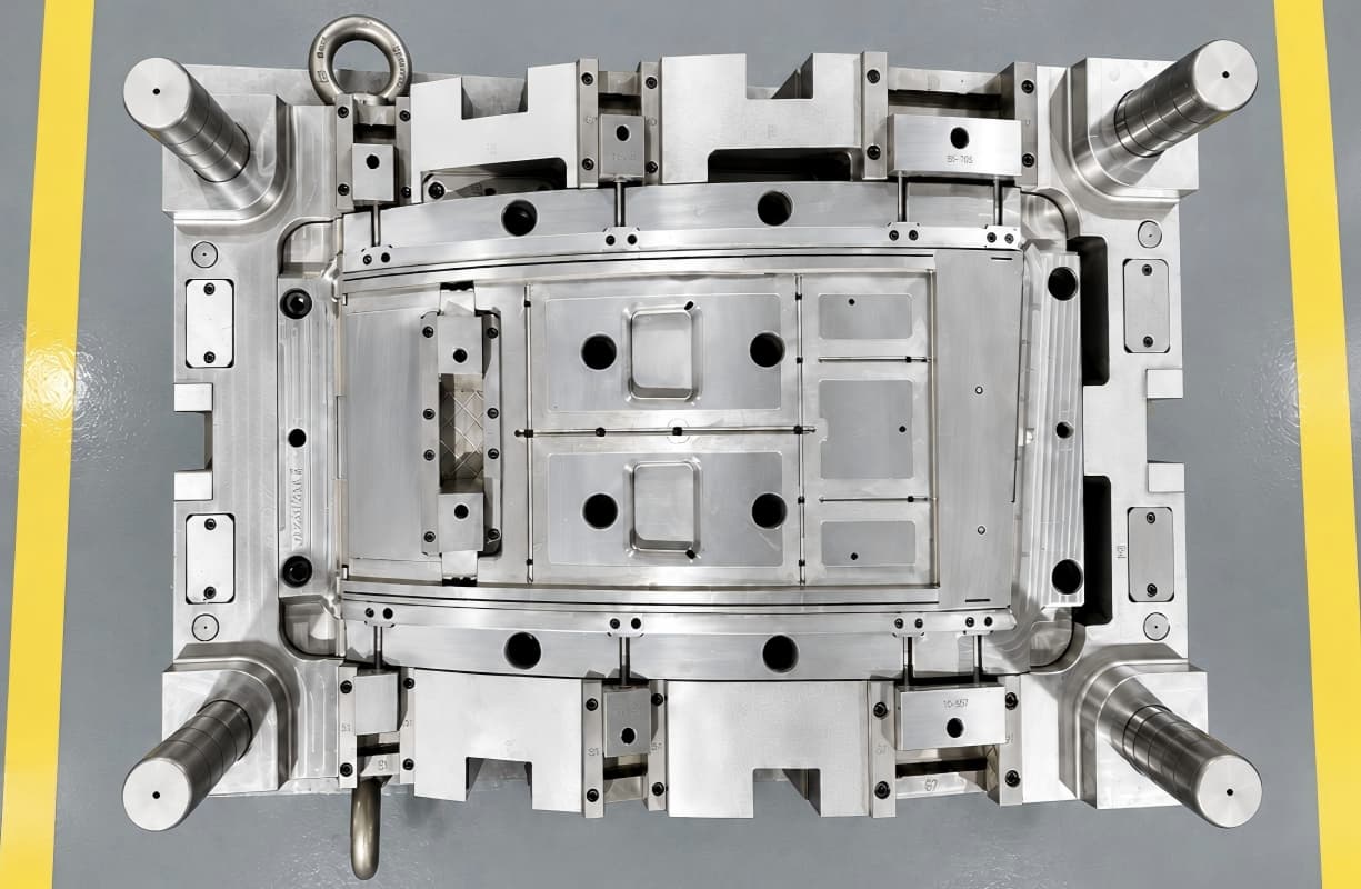
For cosmetic PC parts, specify the texture reference, gloss requirement and permitted gate or ejection marks. Cavity finishing and any polishing are planned around that surface specification. Steel grade, heat treatment and expected maintenance should be stated in the tooling agreement.
Flammability, smoke and toxicity requirements depend on the application and specified material grade. Provide the applicable test specification and evidence requirements; a resin designation alone does not qualify the finished component.
Aerospace Components and Tooling Priorities
Our focus is non-flight-critical aerospace components with defined appearance and assembly requirements. These part families call for different checks during tooling review. Share the installation location and required qualification documents so we can assess the scope before quotation.
Door and Window Housings
Review long cosmetic faces, internal undercuts, texture draft and mounting datums to control visible defects and assembly fit around adjacent cabin panels.
Brackets and Supports
Define fastener loads, insert retention, wall transitions and assembly datums so the proposed polymer bracket can be evaluated against specified service requirements.
Interior Trim
Specify texture, color, edge fit and cosmetic acceptance for bezels and covers, together with applicable cabin material and fire performance test requirements.
Electrical Enclosures
Review board supports, connector openings, sealing features and assembly clearances; any shielding or electrical performance requirement needs a specified material and verification.
Ducting and Ventilation Parts
Check mating flanges, wall distribution, mounting points and operating temperatures so tooling and trial inspection address duct fit and thermal service conditions.
Single-cavity, paired-cavity and family tools are selected around part size, balance, resin and annual demand. Related components sharing a tool need compatible filling and production requirements.
Two Ways to Work With Us
Choose where the mold will run and who will supply the finished parts. Press compatibility, material sourcing, inspection and handover requirements are agreed around that choice. A pre-export trial is an optional validation step for the export route.

Mold Export
What you get
A mold built around your press specifications, resin and agreed tooling standards.
Best for
Teams molding at their own facility with defined machine interfaces and quality requirements.
Molded Part Supply
What you get
Tooling retained for production, with molded parts supplied to your agreed inspection requirements.
Best for
Teams sourcing covers, brackets or housings without managing their own molding production.
Optional Pre-Export Trial
What you get
An agreed production trial to review process settings, sample dimensions and repeatability.
Best for
Export projects requiring a documented run before tooling handover to the receiving factory.
The case below includes a 2,000-piece pre-export trial. Your trial quantity, sample approval criteria and reporting package are agreed separately; a successful trial does not replace validation on the receiving press.
Need a mold for your press or finished aerospace parts? Send your resin grade, quantities and critical requirements for a tooling and production quotation.
Quote My Aerospace ProjectFrom Aerospace Prototype to Production
Before committing to production tooling, identify what the prototype must prove: assembly fit, cosmetic appearance or performance in the specified resin. We support several development routes for aerospace covers and brackets, with the limitations of each method reviewed against the intended test.
CNC Machining
Machine housings or brackets to review interfaces and assembly fit; confirm material availability and differences from molded properties before functional testing.
3D Printing
Print early housing and bracket geometries for clearance checks, connector access and assembly reviews before committing to a detailed tooling design.
Vacuum Casting
Produce short runs of representative covers for appearance and fit reviews, while recognizing that casting resins differ from specified injection-molding grades.
Prototype Mold
Mold initial samples in the specified resin to assess fill, shrinkage and critical dimensions before approving the next production tooling stage.
Prototype approval establishes what has been checked and what remains open. Moving to a new tool, resin grade or production process may require further dimensional, functional or material validation.
Tonnage & Equipment for Large Parts
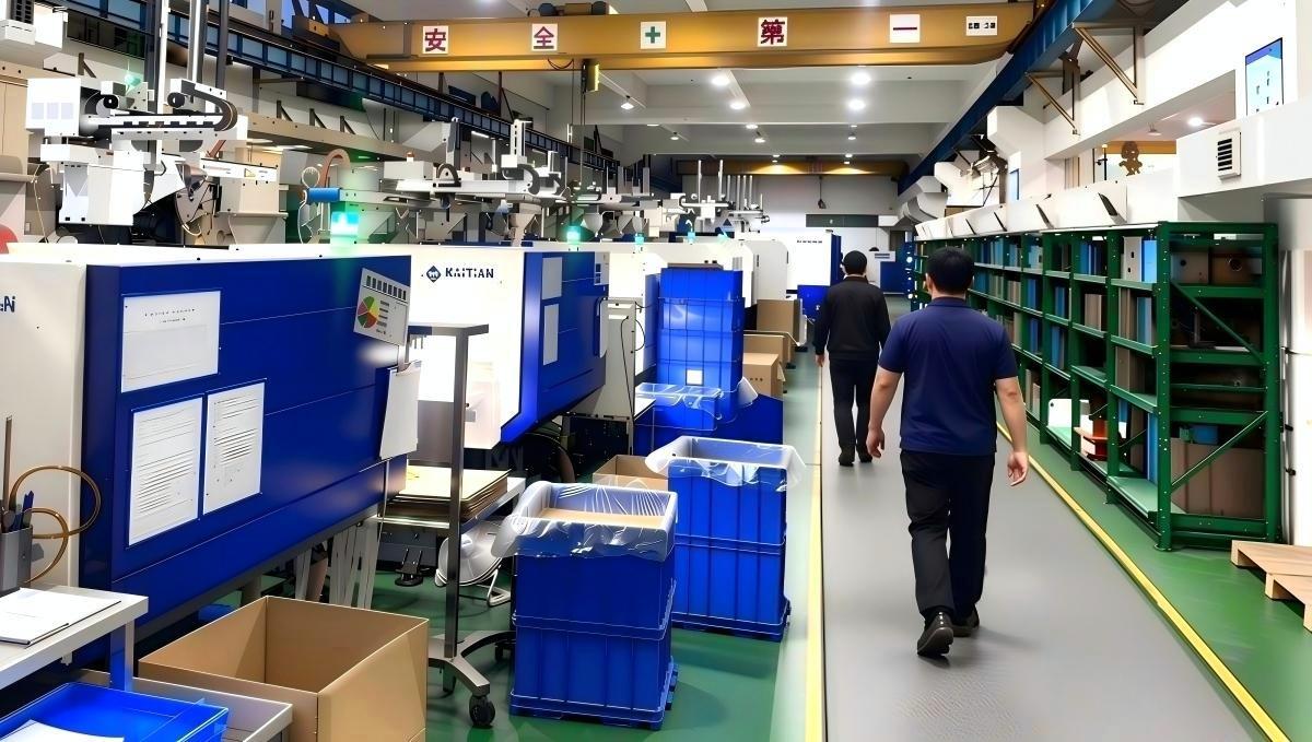
KTM operates 40 in-house injection molding machines from 90T to 400T, with partner capacity up to 3,300T for larger components. For aerospace covers and brackets, press selection also considers mold dimensions, shot size, resin processing temperature and the planned cooling arrangement.
Molding Floor
FANUC, Haitian and LOG presses support in-house molding. Machine selection considers shot size, mold fit and the processing requirements of your specified resin grade.
Partner Presses
Larger presses and specialized two-shot, three-shot or gas-assist equipment are available through partners. The quotation should identify which production steps will use partner facilities.
On-Site Inspection
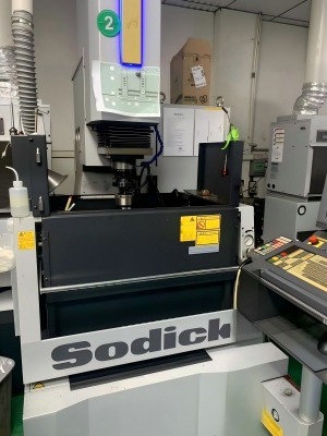
CMM, optical projectors and gauges support drawing-based inspection. Agree critical features, measurement datums and reporting requirements before trial samples or production parts are checked.

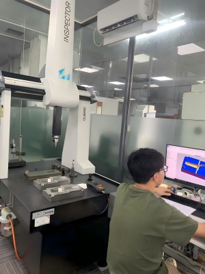
For an export mold, provide platen dimensions, tie-bar spacing, nozzle details and utility connections. For molded-part supply, confirm the approved resin and inspection plan before production release.
Aerospace Injection Molding Case Studies
Four aerospace tooling projects show how part geometry, resin and production location shaped the mold design. Each example identifies the resin, mold steel, cavity layout, tooling challenge and project result.
Case 1: PC Door-Window Housing
Steel: S136
Resin: PC
Surface: VDI-textured, cosmetic
Cavity: 1*1
Challenge: Release an internal undercut in a long, thin-wall housing while meeting the specified cosmetic appearance on its textured face.
Solution: Use a lifter for undercut release and review the gate and cooling layout during DFM around the visible surface.
Result: The project met its cosmetic sink requirement and released the undercut cleanly during the reported run.
Case 2: Exported Bracket Mold
Steel: H13
Resin: PC
Surface: Matte
Cavity: 1*2
Challenge: Balance filling across two PC cavities and prepare the mold for operation on the receiving customer’s press.
Solution: Check runner balance during trials and supply the process sheet with the exported mold for production setup.
Result: Both cavities met the project’s part-weight and dimensional requirements on the customer’s production floor.

Case 3: PEEK Air-Management Bracket
Steel: 1.2344
Resin: PEEK
Surface: Functional, non-cosmetic
Cavity: 1+1
Challenge: Control shrinkage and dimensions in a PEEK bracket specified for service involving temperature changes.
Solution: Review thermal control around the wall distribution and compensate shrinkage in the tooling using simulation and trial findings.
Result: Dimensions met the project’s agreed requirements after thermal conditioning; the mold was exported with trial documentation.
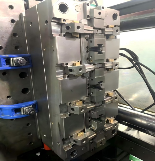
Case 4: Cover Mold with Trial Run
Steel: H13
Resin: PC
Surface: Cosmetic
Cavity: 1+1
Challenge: Assess production consistency on a cosmetic PC cover before handing the mold over for export.
Solution: Run a documented 2,000-piece trial and record dimensions for review against the agreed acceptance requirements.
Result: Trial samples were validated against the project’s agreed acceptance requirements; the mold shipped with trial and CMM reports.
Engineering Review & Quality Documentation
For an aerospace housing or bracket, useful quality documentation connects the drawing requirements to tooling decisions and trial results. Our engineering team reviews the following items with your project team so the requested evidence is defined before manufacture, including any supplier approval requirements.
DFM Report
Identify sink-prone bosses, texture draft, undercuts and critical assembly datums before tooling. Preliminary feedback supports quotation; detailed DFM follows the agreed project review scope.
Moldflow
Assess filling, weld-line location and warpage where geometry or material creates significant molding risk. Agree the analysis scope and assumptions before simulation work starts.
Mold Trial Report
Record molding settings, sample observations and trial findings for engineering review. Track required tool changes against the drawing revision and agreed sample acceptance criteria.
Dimensional Verification
Measure agreed critical features using suitable dimensional inspection methods. Identify datums, tolerances and conditioning requirements so the report supports review of fit and function.
Material Certificates
Define resin grade, permitted substitutions and required material records. Agree steel certification and batch traceability requirements during quotation so documentation matches the purchasing specification.
Founder-Led Engineering
Our founder brings 20+ years of tooling experience to difficult design decisions. Gate, cooling and release questions are reviewed directly by the technical team.
A dimensional report shows what was measured under stated conditions. Functional testing, environmental exposure and any first article inspection requirements must be defined separately when the program requires them.
We operate under ISO 9001. Share your supplier quality requirements before ordering, including required records, sample approval, change control and production release responsibilities. The documentation package should match the scope agreed with your quality team.
Request the relevant certificate scope and project documentation during supplier evaluation. Any gap between your requirements and the proposed supply route should be resolved before tooling begins.
Aerospace Injection Molding FAQ
Is KTM AS9100 certified?
KTM operates under ISO 9001 and is not currently AS9100 certified. Our focus is selected non-flight-critical components. Supplier qualification depends on your program and purchasing requirements; non-flight-critical status alone does not waive them. Tell us if AS9100 or a specific customer approval is mandatory before sending the project for quotation.
Can you meet our cosmetic and dimensional requirements?
Send the drawing with datums, tolerances, visible faces and texture references marked. We review sink, warpage, weld lines and ejection marks during DFM, then agree sample inspection and appearance criteria. Achievable tolerances depend on geometry, resin and specified measurement conditions; we confirm the critical features during project review and trials.
Can you use our specified resin and meet FST requirements?
Our project examples include PC and PEEK. For any grade, provide the manufacturer, filler content and approved substitutions, if allowed. Include the applicable flammability, smoke and toxicity specifications and required test evidence. Material datasheets help the review, but suitability and finished-part compliance must be established against your specific application requirements.
What samples and inspection documents can we agree before production?
Define the sample quantity, critical dimensions, material records and required reporting format during quotation. Trial documentation can cover settings, sample observations and dimensional results. If you require a formal first article inspection package or environmental testing, state the specification early so scope, responsibility and availability can be confirmed before ordering.
What determines cost, minimum quantity and lead time?
Size, resin, cavity count, steel, undercuts, finish and inspection scope determine the quotation. Give prototype and annual quantities so tooling economics can be assessed; minimum quantities and dates are confirmed per project. Separate tool manufacture, sampling, approval, production and shipping. Changes affecting price or schedule should be agreed in writing.
Can we buy an export mold or order finished parts?
Both routes are available. For mold export, provide your press specifications, utility connections and tooling standards; agree trial and handover documents. For finished parts, specify resin, quantities, packaging and inspection requirements. Identify any required approval of the molding facility so the proposed in-house or partner production route can be assessed.
Discuss Your Aerospace Part & Get Preliminary DFM Feedback
Tell us where your aerospace cover, bracket or housing will be installed. Include the resin grade, quantities, critical dimensions and surface requirements. Our team sends an initial reply within one working day to confirm the next steps. Detailed DFM and quotation timing depends on the project scope and information provided.
Request DFM Feedback
What to Include in Your Inquiry
Part requirements: drawing revision, overall dimensions, assembly datums, tolerances and surfaces with cosmetic or texture requirements.
Material and approval: exact resin grade, filler content, operating conditions and any supplier qualification or FST requirements.
Supply plan: export mold or finished parts, initial order and annual quantities, target sample date, repeat-order schedule and packaging requirements. For export tooling, include your mold standard, expected tool life and spare-parts requirements.
Engineering review: we assess sink, warpage and release risks, clarify missing details, then define the quotation and trial scope.