20+ years
Practical moldmaking experience
CUSTOM TOOLING & MOLDED PARTS
Add a soft grip, integrated seal or protective surface to your rigid component. KTM builds overmolding tools and supplies custom parts, with material pairing, shut-off geometry and production requirements reviewed together.
Tool export or molded-part supply. Preliminary feasibility at quotation; detailed DFM after project launch. An NDA can be arranged before you share drawings.

Practical moldmaking experience
In-house molding capacity
Project-specific quality documentation
Tools or parts
UNDERSTANDING THE OVERMOLDING PROCESS & FAILURES
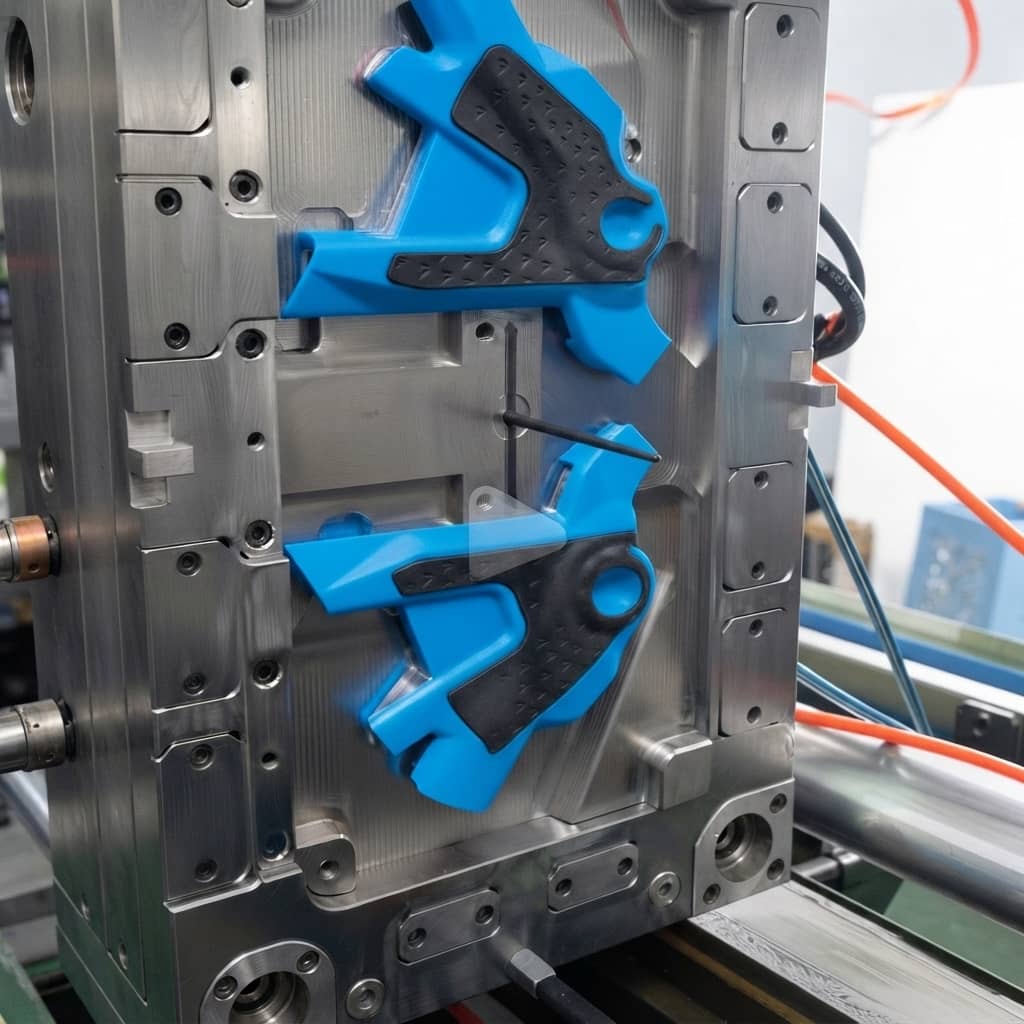
Overmolding forms a second material over a preformed substrate to combine functions in one component. Plastic overmolding commonly adds a TPE or TPU grip or seal to a rigid plastic base; rigid-on-rigid and metal-insert designs require their own material and tooling review.
Material adhesion: compatible substrate and overmold grades can develop a bond at the interface during molding. For example, TPE compounds formulated for PP adhesion can bond to suitable PP grades. The result depends on the exact resin pair, additives, surface condition and processing window; similar polymer polarity alone does not establish bond strength.
Mechanical interlocks: when the grades do not bond adequately, undercuts, dovetail grooves, wraparound features or through-holes give the overmold something to lock into. These features can also reinforce an adhesive interface. Surface texture alone should not be treated as a substitute for a designed interlock.
Thermal and trial checks: the substrate needs sufficient stiffness and support under second-shot heat and pressure. Set melt, mold and substrate temperatures from the exact supplier data, then verify adhesion or retention with representative trial parts. DFM identifies risks; it cannot certify the finished bond before molding.
| Failure | What to investigate | Design and trial response |
|---|---|---|
| Overmolding delamination | Grade compatibility, contamination, exposed grip edges and service loads. | Check supplier adhesion data; design retention where needed; agree peel or pull testing and conditioning. |
| Substrate warpage | First-shot stiffness, locating support, pressure and differential shrinkage. | Review support and gating; establish a processing window and measure the molded part after agreed conditioning. |
| Flash at shut-offs | Substrate variation, seating, worn tooling and local sealing pressure. | Define locating datums and shut-off contact; inspect fit and flash on critical surfaces during trials. |
| Short shots, sink or flow marks | Wall transitions, flow length, gate location, venting and packing. | Balance filling and venting; core thick regions where practical; assess simulation when geometry warrants it. |
| Ejection damage | Draft, texture, cooling and ejector contact on soft or unsupported areas. | Set release geometry and support; tune cooling and ejection without compromising the finished surface. |
For overmolding troubleshooting, send defect photos, exact material grades, part geometry and available process settings. The same visible defect can have different causes.
APPLICATIONS
Overmolded parts earn their place when one component does two jobs: rigid where it carries load, soft where a hand, a gasket, or a vibration source meets it. Start with the function your part needs, then specify the substrate, soft material and acceptance tests. These application examples show where a bonded or mechanically retained second layer can add value.

Medical device overmolding and reusable product grips require careful material selection against cleaning agents, skin contact and operating conditions. Define the applicable product requirements, grip hardness and retention loads so the tooling and validation plan address the component’s actual use.

Automotive overmolding can combine rigid housings with compliant contact surfaces or sealing features. Review temperature cycling, fluid exposure and assembly loads alongside resin grades. Define appearance limits and dimensional datums so trial parts can be assessed against the intended installation.

Plastic overmolding can add protective edges or integrated seals to electronic housings. Review joint geometry, seal compression and mating surfaces with the enclosure design. Specify the required ingress test and service environment before selecting the elastomer and approving the tool.

TPE overmolding and TPU overmolding add grip surfaces to tools and personal-care products. Evaluate abrasion, wet handling, cleaning exposure and edge retention. Match hardness and surface texture to the user’s contact area, then validate the grip on representative molded samples.
Need a waterproof overmold? An integrated seal can reduce separate assembly steps, but the complete enclosure still needs testing. Define mating geometry, compression and the required IP67 or IP68 test conditions; molding a soft layer alone does not establish an ingress rating.
KTM MANUFACTURING CAPABILITY
KTM is an engineering-led overmolding company in Dongguan, China. Our own toolroom and injection molding operation support projects from mold design through molded-part supply, with the manufacturing route and trial arrangements identified for your project.
In-house injection molding capacity
In-house clamping force range
Founder’s practical moldmaking experience

A clean shut-off is what keeps your second shot off the surfaces it shouldn’t touch. FANUC CNC machining, SODICK EDM, mold fitting and dimensional inspection support accurate shut-off and locating features. KTM manufactures overmolding and two-shot molds in-house. We do not own a dedicated 2K injection machine; specialist partners assist with two-shot mold trials.
Insert/transfer overmolding uses a separately loaded substrate and a suitable single-shot press. The tool, press size, loading method and production location are confirmed against the part and order scope. Larger presses are available through our partner network when required.
Our inspection equipment includes CMM, optical measurement, gauges and steel-hardness testing. We agree critical dimensions, measurement datums and sample conditioning for each part. Soft surfaces may require optical or functional checks to avoid measurement deformation.
Your project document set: preliminary feasibility feedback at quotation; detailed DFM after project launch; Moldflow analysis when geometry or customer requirements justify it; agreed trial and dimensional reports; material documentation and traceability within the project scope. Request company ISO certification and the relevant quality documents during supplier qualification. Inspection and acceptance requirements follow your project scope.
OVERMOLDING PROCESS
Both routes can produce a multi-material part. The choice depends on substrate geometry, material grades, loading access, design stability and the expected production quantity.

The preformed substrate is placed into an overmolding tool for the second material. This can accommodate existing inserts, separate surface preparation and designs unsuitable for a rotary tool. Include substrate handling, locating repeatability and contamination control in the cost and quality plan.
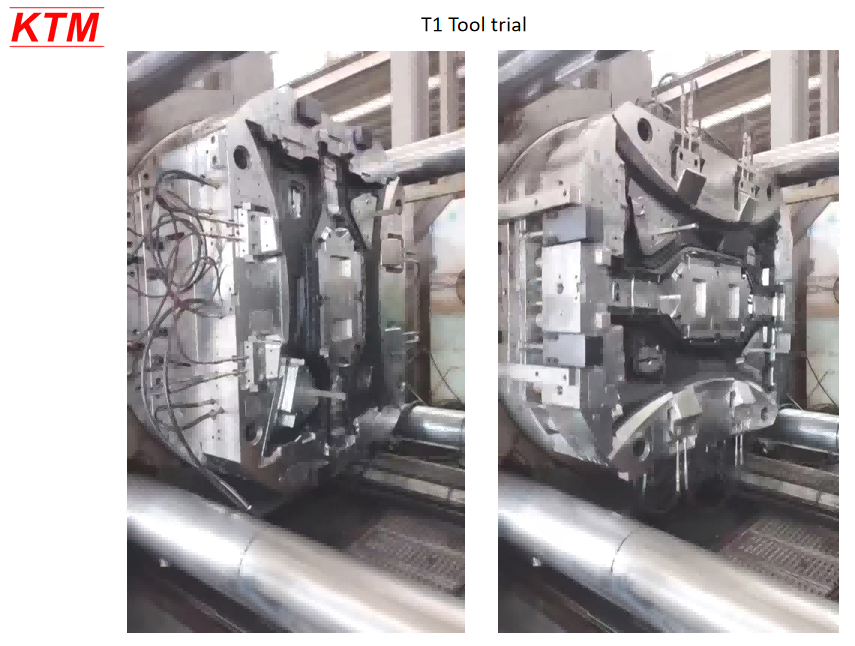
A dedicated two-shot press applies both materials within an integrated cycle using a suitable rotation, transfer or core-back arrangement. This reduces separate handling but requires compatible part geometry, tooling and press interfaces. KTM builds the 2K mold; our partners support the two-shot trial.
Check the first-shot material, critical dimensions and cleanliness. Establish drying or conditioning requirements from supplier data, and provide stable support for the areas exposed to second-shot pressure.
Position the substrate on repeatable datums. Review manual or robotic loading for transfer molding, or the rotation and transfer arrangement for a two-shot tool before trial sampling.
Control filling around the substrate through the selected gates and vents. Set melt, mold and insert temperatures within the validated material window, then tune packing and cooling.
Examine shut-offs, grip edges and critical dimensions. Evaluate adhesion or retention using the agreed method, and document approved samples and settings before releasing the project for production.
Prototype and low-volume overmolding still need representative resin grades and interface testing. A prototype made with different materials cannot establish production bond strength.
PROCESS COMPARISON
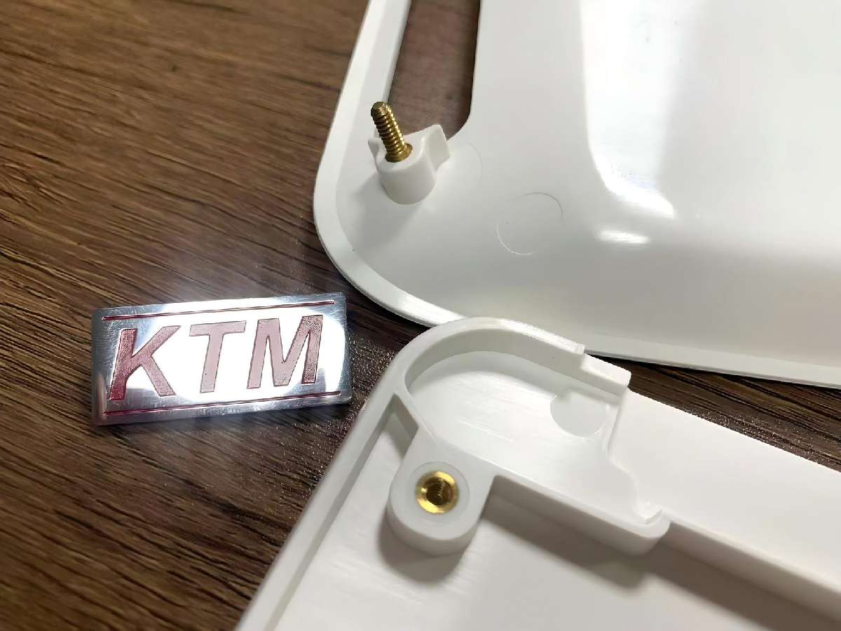
These terms overlap. Overmolding describes adding material to a substrate; insert molding describes molding around a preplaced component; two-shot molding describes an integrated machine route. A transferred plastic substrate can therefore be both an insert and an overmolding substrate.

| Decision point | Overmolding | Insert molding |
|---|---|---|
| Typical purpose | Add grip, sealing, protection or another material function. | Integrate a preformed component, often metal, into a molded part. |
| Substrate | Rigid plastic, metal or another suitable preformed component. | Metal, plastic, ceramic or another suitable insert. |
| Retention | Grade-dependent adhesion, mechanical retention or both. | Often mechanical retention; bonding depends on the materials. |
| Tooling focus | Interface geometry, coverage, shut-offs and shrinkage. | Insert location, retention, support and encapsulation. |
| Decision point | Insert / Transfer Overmolding | Two-Shot / 2K |
|---|---|---|
| Equipment | Suitable single-shot press with substrate loading. | Dedicated multi-material press and compatible tooling. |
| Tool arrangement | A separate overmold tool; first-shot tooling if needed. | Coordinated cavities with rotation, transfer or core-back. |
| Good fit | Preformed substrates, flexible batches and changing designs. | Repeat programs where automation and volume justify tooling. |
| Cost assessment | Include substrate supply, handling, cycle time and yield. | Include tool complexity, press cost, cycle time and yield. |
There is no universal volume threshold or percentage saving. We compare tooling investment and quoted unit price at your batch and forecast volumes. For related capabilities, see insert molding and 2K two-shot molding.
MATERIAL EXPERTISE
Overmolding material compatibility starts with the two exact grades and the part’s function. Hardness, additives, color carrier, moisture and surface condition can change adhesion even when the polymer family names stay the same.
For TPE overmolding, select a compound formulated for the intended substrate and service conditions. TPU overmolding also requires grade-specific bonding and processing checks. A soft material that feels right in a hand sample may still peel, distort the base or miss a seal requirement.
Silicone overmolding follows a different curing process. Confirm that the substrate tolerates the cure conditions and that the selected LSR uses a suitable adhesion system, surface treatment or mechanical retention. Thermoplastic bonding assumptions do not transfer automatically to silicone.
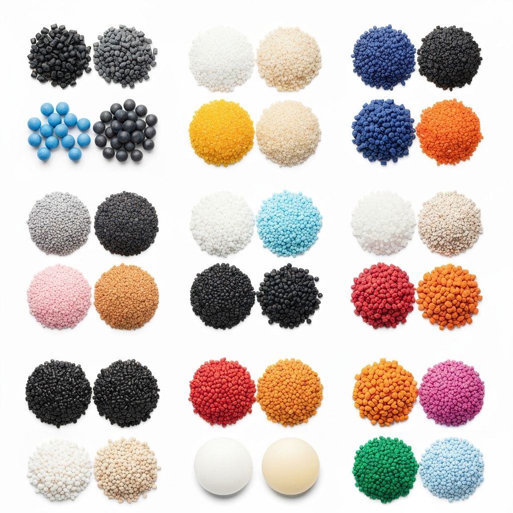
Choose the overmold against the exact substrate grade and its specified additives. Supplier compatibility data narrows the options; representative molded samples establish whether the interface meets the strength and service conditions required for your component.
Use holes, undercuts or wraparound features where adhesion is limited or repeated service loads need reinforcement. Review these features with substrate strength and mold release so retention improves without creating fragile sections or difficult tooling.
Control moisture, mold-release residue and handling contamination before the second shot. Surface texture or treatment may help or hinder adhesion depending on the grade pair; validate the actual surface instead of assuming rougher bonds better.
| Substrate | Overmold candidates to evaluate | What must be confirmed |
|---|---|---|
| ABS, PC and PC/ABS | Bonding-grade TPE; selected TPU grades. | Supplier data for both exact grades, color/additives, interface strength and distortion. |
| PP | TPE compounds specifically formulated for PP adhesion. | Grade compatibility, surface condition and retention under the intended load. |
| PA / glass-filled nylon | Specialty TPE or TPU systems validated for the PA grade. | Moisture conditioning, glass content, surface quality and dimensional change. |
| PBT | Selected adhesion-modified TPE or TPU grades. | Exact-grade adhesion data and trials; mechanical retention where required. |
| POM | Specialty systems where supplier data supports bonding. | Do not assume adhesion; assess mechanical retention and validate the interface. |
| Metal inserts | Selected TPE/TPU or silicone systems. | Mechanical locking, insert cleanliness, corrosion concerns and any surface treatment. |
| Substrates for LSR | Cure-compatible plastics or metals. | Cure temperature, self-bonding grade or primer, retention and part validation. |
Combinations such as PC with ABS, PC with PMMA, or ABS with SAN require exact-grade and process validation. Review appearance, differential shrinkage and interface loading together. For pairs with insufficient adhesion, assess a deliberate mechanical joint; a broad compatibility chart cannot replace testing.
Agree peel or pull geometry, loading direction, controlled sample conditioning and failure criteria. Record whether separation occurs at the interface or within the material, so results from different samples can be compared consistently.
Identify critical datums, shut-off boundaries, flash limits and cosmetic surfaces on the drawing. Select CMM, optical or functional inspection as appropriate, and define the conditioning interval before accepting dimensional measurements from molded samples.
Specify temperature, chemicals, moisture, repeated flexing and seal requirements before grade selection. Agree the applicable product tests and responsible party, then assess representative parts after exposure when the intended use requires durability evidence.
Set melt, mold and substrate temperatures from the exact resin supplier data, then confirm the process window in trials.
| Record field | What to record before release |
|---|---|
| Part and revision | Drawing revision, cavity identification, sample quantity and trial date. |
| Material pair | Exact substrate and overmold grades, color/additives and lot references. |
| Dimensions and appearance | Measured critical features, conditioning, inspection method, flash limits and agreed surface standard. |
| Interface performance | Peel/pull specimen and direction, exposure conditions, acceptance target, result and failure mode. |
| Release decision | Open issues, required corrections, approved sample reference and dated customer sign-off. |
This is an example checklist for agreeing your project records, not a test report or a claim that every application needs the same tests.
Overmolding bonding agents, primers or surface treatments are considered only where the material supplier supports the specific combination. Overmolding adhesion failure still requires a review of material grades, surface preparation and test conditions; a primer cannot correct every unsuitable joint design.
Send the substrate grade, preferred overmold, drawing and operating conditions. We will review the proposed bonding route, retention features and information needed for a useful quotation.
Preliminary DFM feedback • NDA available • Exact-grade review
DESIGN & DFM
A useful overmolding design review connects the material pair to geometry, mold construction and inspection. The starting guidelines below are refined for your exact resins, operating environment and production route.
These six design checks address the interface, substrate and tool. Review them together to reduce flash at the shut-off, sink in thick sections, ejection damage and peeling at exposed edges.
For many TPE applications, 1.5–3.0 mm (0.060–0.120 in) is a useful starting range. Keep transitions gradual; confirm minimum sections against hardness, grade flow and flow length.
A rigid section around twice the soft-layer thickness is a starting check, not a universal rule. Review ribs, cavity support, differential shrinkage and molding pressure before deciding whether the substrate resists distortion.
Long draws in soft materials may need 3–5° draft. Set the final angle against texture, draw depth, shut-offs and ejection so the overmold releases without dragging or tearing at exposed edges.
Replace sharp internal transitions with practical radii and avoid abrupt changes in section. Check flow, local stress and tool access; small functional details may need different geometry from a broad grip surface.
Plan overmolding gate design around filling, weld lines and the substrate’s support. Define positive sealing contact at shut-offs, protect critical functional surfaces and properly vent the final cavity areas that fill last.
Use mechanical interlocks where the interface or service load needs reinforcement. Review predicted overmolding shrinkage for both selected materials and protect peel-prone edges without creating weak substrate sections or obstructing mold release.
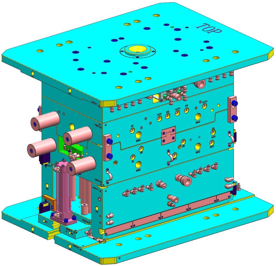
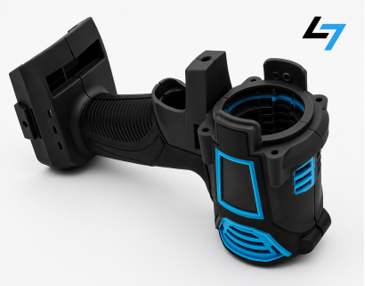
Set these requirements on the drawing before tooling: coverage boundaries, material grades, critical dimensions and acceptance tests. Use the trial to confirm the remaining material and process decisions.
For overmolding tolerances, separate rigid datum features from soft surfaces. The achievable limits depend on shrinkage, part size, conditioning and the measurement method; we confirm critical features during DFM rather than applying one tolerance to the whole component.
Technical references: Avient part-design guidance, Avient processing guidance and Teknor Apex adhesion testing. These guide engineering review; project acceptance follows the approved drawing and test plan.
PROJECT EXPERIENCE
KTM has completed a toothbrush project with 250,000 pieces delivered. The project volume below is cumulative. The accompanying design example explains what to evaluate for a rigid multi-material component.
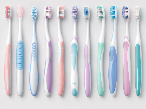
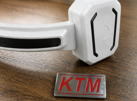
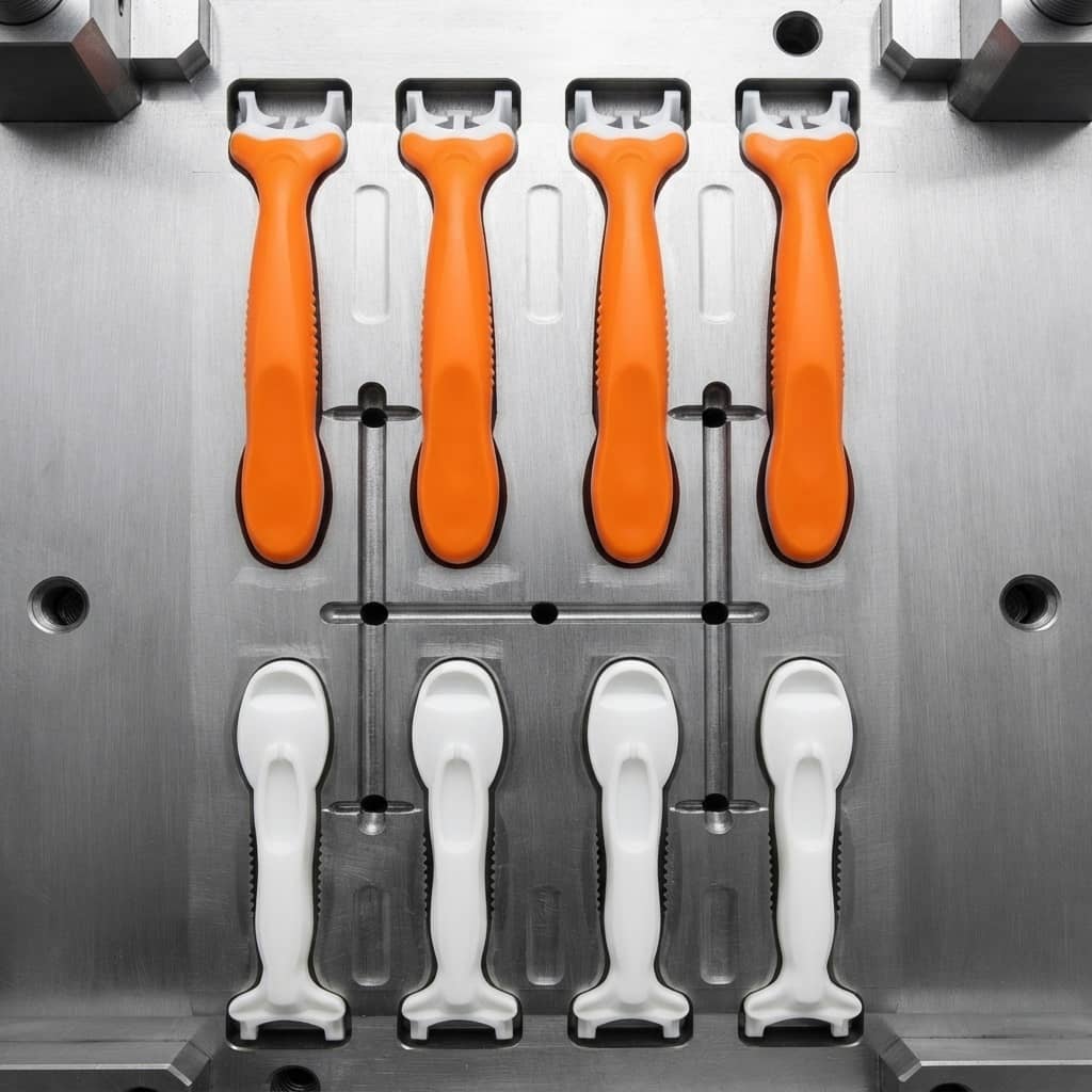
250,000 pieces delivered. KTM completed this toothbrush project with a 2+2 cavity layout. For a new handle, review exact resin grades, wet-use conditions, edge retention and appearance requirements before agreeing the production tooling details and approving representative samples.
A rigid-on-rigid shell needs a validated joint between the chosen grades. Review differential shrinkage, weld lines and interface loading, then agree any impact or durability tests for the finished assembly. Product-specific performance must be established by its own test results.
Material grades, mold steel, cavity configuration and delivery schedule are specified for each new project. The delivered quantity above does not establish a universal bond-strength, impact or defect-rate guarantee.
WHY KTM
When comparing overmolding manufacturers in China, check who builds the tool, runs the trial and resolves interface problems. KTM’s overmolding factory combines engineering-led moldmaking with project communication and an agreed scope for each order.
KTM’s founder trained in mold design and manufacturing and has over twenty years of moldmaking experience. Our engineers review documented tooling and specific molding trial issues; the project team coordinates clear English communication and the next agreed actions.
Your quotation identifies the proposed molding route, tooling scope and planned trial arrangement. KTM manufactures the mold in-house, with partner support for dedicated two-shot trials, so responsibilities and required machine interfaces are clear before the tool is built.
Review detailed DFM after project launch, then assess representative trial samples and the agreed reports. Resolve interface, dimensional and appearance issues against documented acceptance criteria before approving production, keeping drawing revisions and sample decisions aligned throughout the project.
Tooling investment and molded-part prices are quoted separately against the agreed scope and quantities. Changes to drawings, material requirements or delivery scope are reviewed before proceeding, so their cost and project timing effects can be discussed and documented.
KTM supports small batches and repeat production without a fixed minimum order quantity. Request an export mold for your own presses or molded-part supply, and include the destination machine requirements when the tool will run at your facility.
Agree approved samples, material records and inspection requirements for the order. For repeat production runs, keep the drawing revision, resin grades and critical process information aligned, and review material or tooling changes before they affect the overmolded interface.
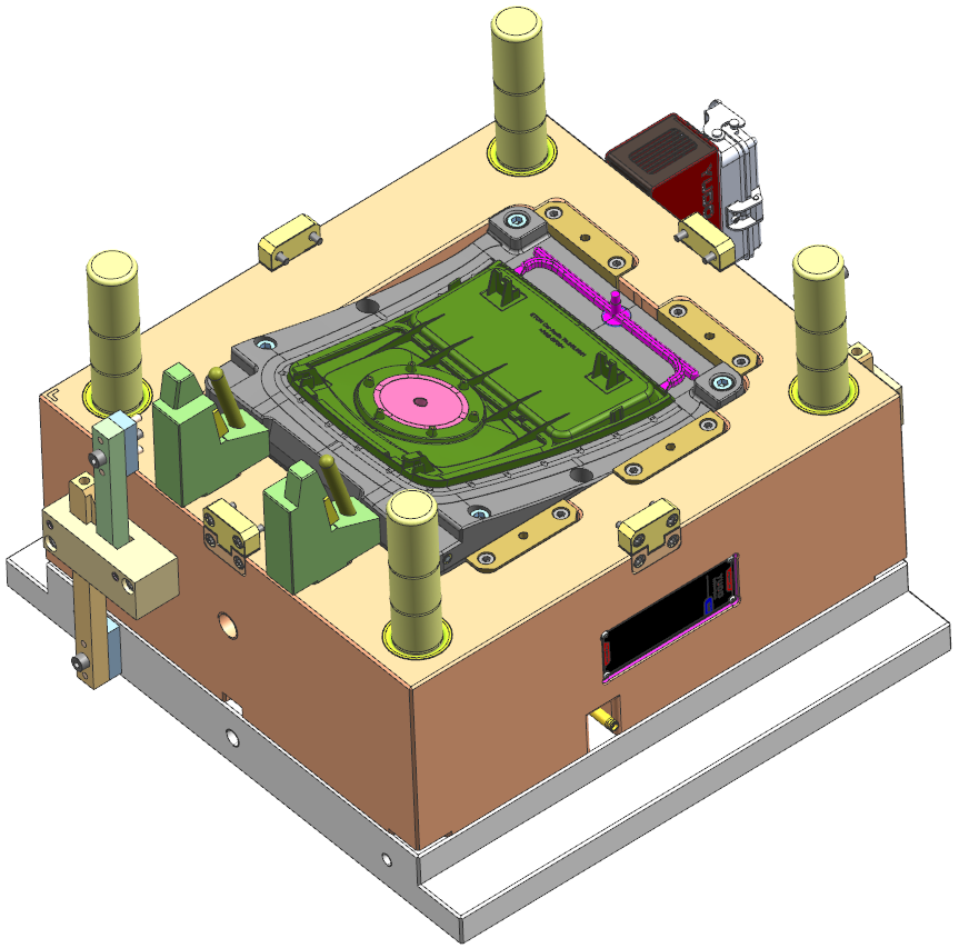
For export molds, identify the receiving press, mounting and nozzle interfaces, transfer mechanism, utilities and preferred mold standards. These details are particularly important when a two-shot tool will run on your own machine.
Send your geometry, material pair and forecast quantity. We will review tooling requirements, the proposed production route and the information needed to quote the mold and parts separately.
Early in development? Share the application and performance targets; final material selection can follow the feasibility review.
Common questions about overmolding
START YOUR PROJECT
Tell us what your part must do and where it will be used. We will review the material pair, tooling route and missing specifications before preparing a project-specific quotation.
You receive preliminary feasibility feedback and the proposed tooling and production scope. Detailed DFM follows project launch; trial samples and agreed reports support your approval before production. An NDA can be arranged before confidential drawings are shared.