Insert Molding Services in China for Custom Metal–Plastic Parts
KTM machines your metal inserts, builds the mold, and molds your finished parts under one engineering team. Get a coordinated review of insert fit, retention, and thread protection, plus an itemized project quote.
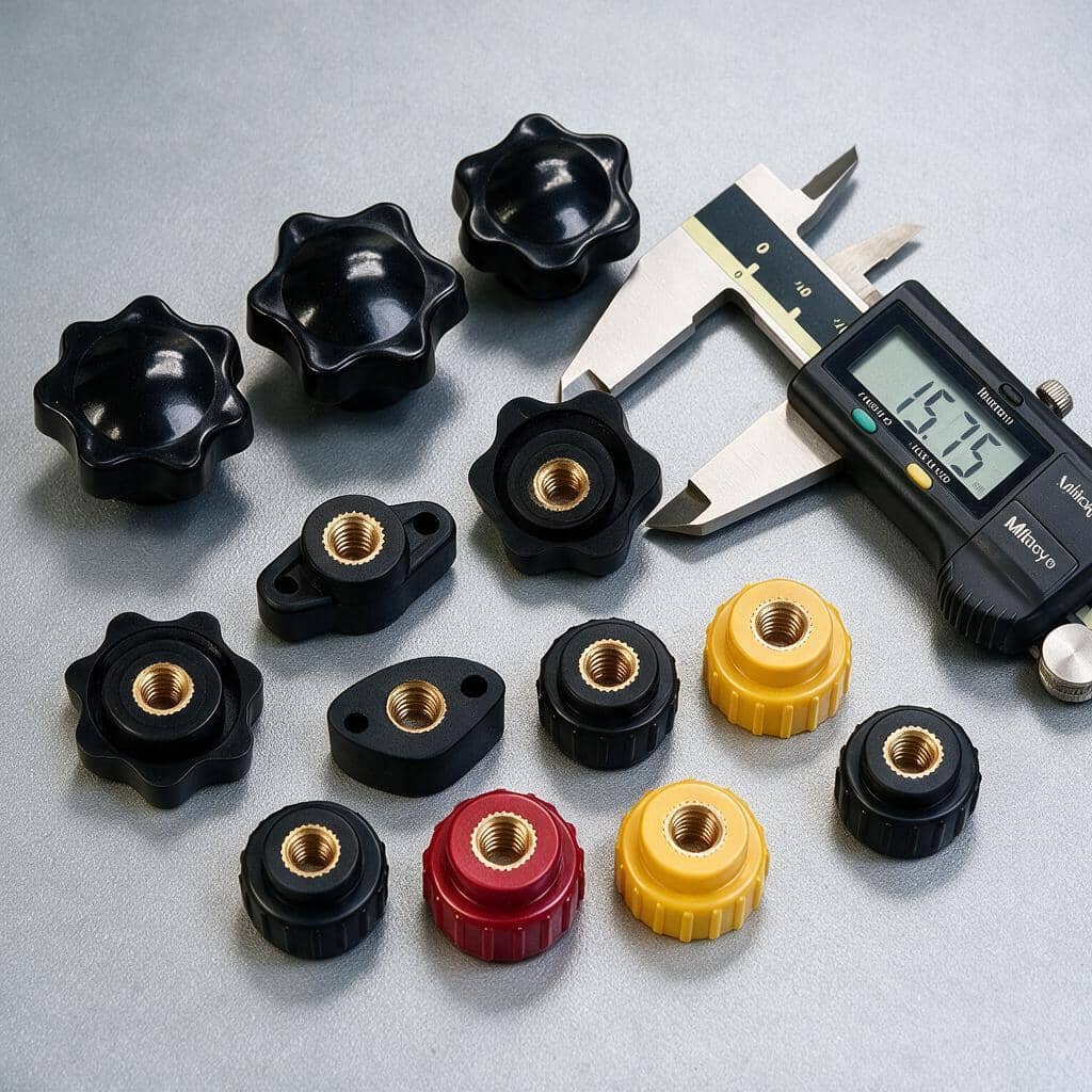
Metal inserts. Mold making. Injection molding. One engineering team.
What Is Insert Molding? A Working Definition for Engineers
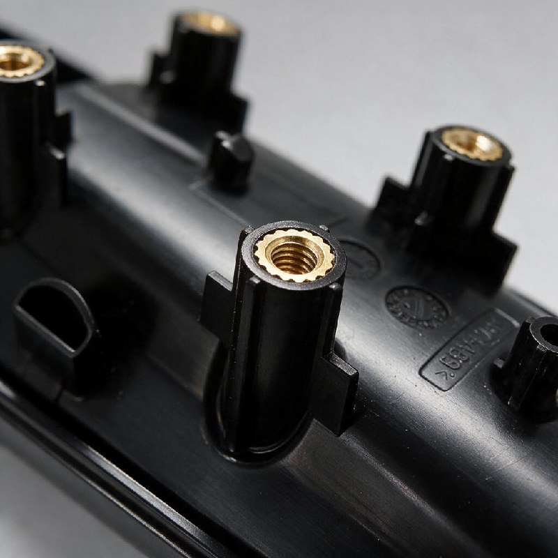
Insert molding is an injection molding process in which a pre-made component — most often a metal insert such as a brass threaded bushing, stainless pin, or stamped terminal — is loaded into the mold cavity before resin is injected. The plastic encapsulates the insert under controlled pressure and cools around it, producing a single part with the metal mechanically anchored inside.
The four-step cycle:
1. Insert loaded into the cavity (manual or robot-fed) 2. Mold closes; resin injected around the insert under controlled pressure and temperature 3. Part cools; resin shrinks onto the insert's retention feature (knurl, groove, or undercut) 4. Finished part ejects with the insert locked in placeChoose insert molding when a metal thread, locating feature, or electrical contact needs to become part of a molded component. Retention depends on insert geometry, surrounding plastic, and service loads; it must be validated for the application. For soft grips, seals, or a second molded layer, explore our overmolding services. The processes can overlap, so we review the part's function before recommending either route.
Insert molding can eliminate a separate insertion or fastening operation. Compare that benefit against insert loading, tooling complexity, and the required retention tests before choosing the process.
The next decision is who will coordinate the insert, mold, and molding process. ↓
Metal Inserts, Mold Making, and Molding in One Factory
A metal insert can meet its own drawing and still cause flash, difficult loading, or position variation in the mold. Coordinating the insert tolerance, locating pocket, and molding conditions helps address these interface problems before production approval.
When comparing insert molding companies, ask who owns the fit review and correction plan. At KTM, one engineering team coordinates insert machining, mold building, and molding. The table shows the decisions to align when these operations are handled by separate suppliers or by one insert molding factory in China.
| Decision Point | With Separate Suppliers | With KTM's Integrated Team |
|---|---|---|
| Insert doesn't fit the mold | Agree which supplier checks the insert-to-pocket fit and manages corrections. | Review the insert and pocket together, then assign the required machining or tooling correction. |
| Lead time | Coordinate insert availability, mold completion, and the molding trial across suppliers. | Plan insert machining and mold work in parallel where the approved design allows. |
| DFM coverage | Combine separate reviews into one agreed tolerance and process plan. | Review insert geometry, tooling, resin flow, and loading in one DFM process. |
| Mid-build change orders | Confirm how each supplier's cost and schedule will change. | Document the cost and schedule impact for your approval before changed work starts. |
| Cost transparency | Reconcile tooling, insert, molding, and inspection scopes across quotations. | Separate tooling, inserts, molding, and agreed extras in one itemized quotation. |
Choose the service scope that fits your project and existing supplier arrangements. ↓
Our Insert Molding Services: Inserts, Tooling, and Production
We review the insert-to-mold tolerance stack in CAD before machining. Once the inserts and tool are made, we check their physical fit and use trial parts to verify the finished dimensions.
1 In-House Metal Insert Machining
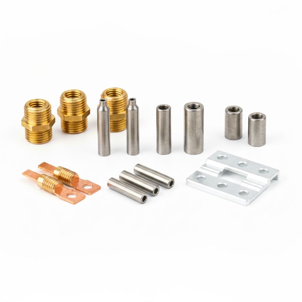
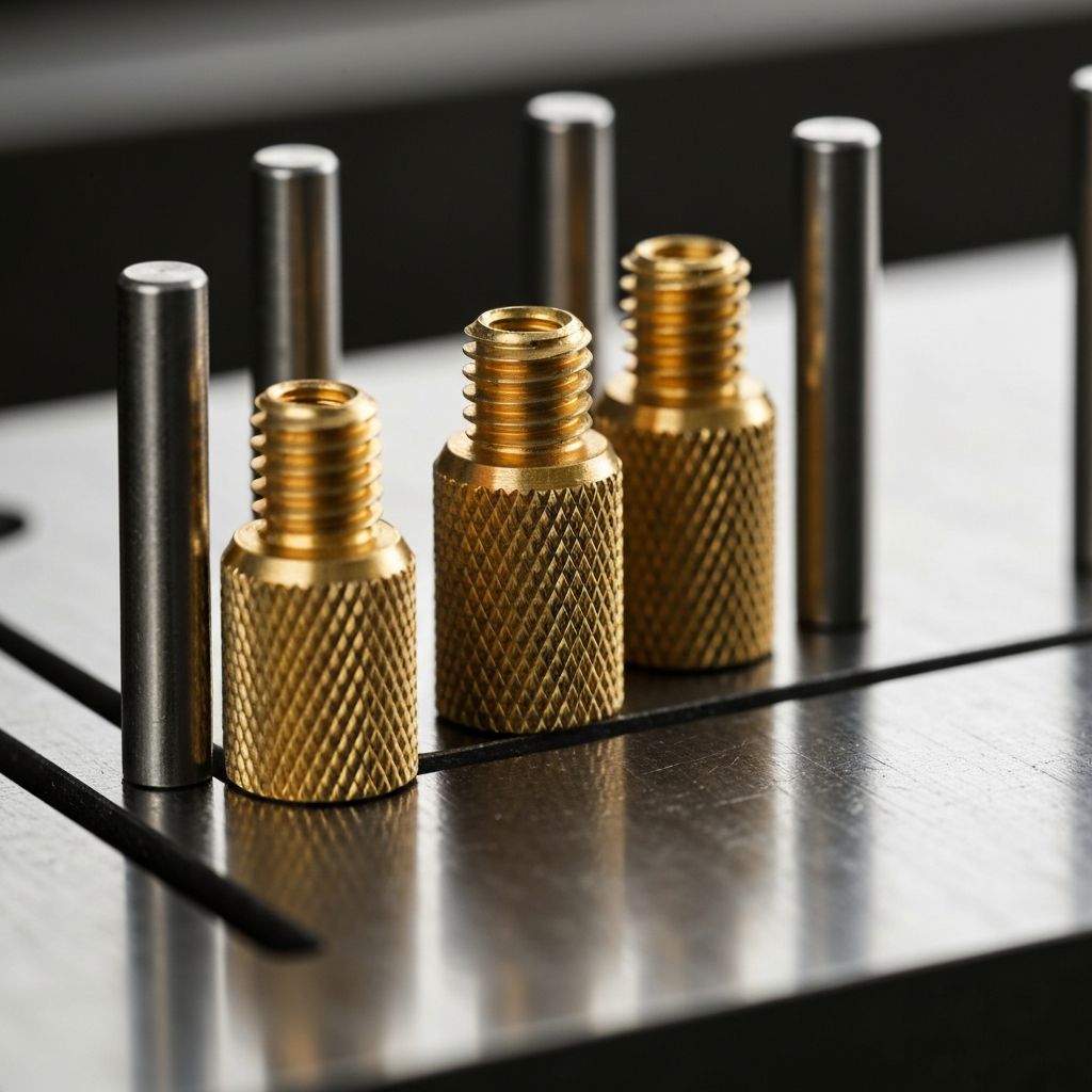
We machine brass bushings, stainless pins, copper terminals, and aluminum inserts to the agreed drawing. The review covers locating surfaces, retention features, thread protection, and any coating allowance. Specialty finishes or externally sourced features are identified in the quote, with incoming checks agreed before use. You can keep a qualified insert supplier or include insert manufacture in KTM's scope.
Three sourcing paths, decided at the quote stage:
- KTM-machined inserts—include the insert drawing, alloy, thread specification, and finish so we can review machining and mold fit together.
- Customer-supplied inserts—send drawings and representative samples for incoming inspection and fit checks before trials, whether the tool stays here or is exported.
- Catalog inserts—provide the manufacturer and exact part number. We check that the selected product is intended for molding in and confirm sourcing before purchase.
2 Insert Mold Design & Build
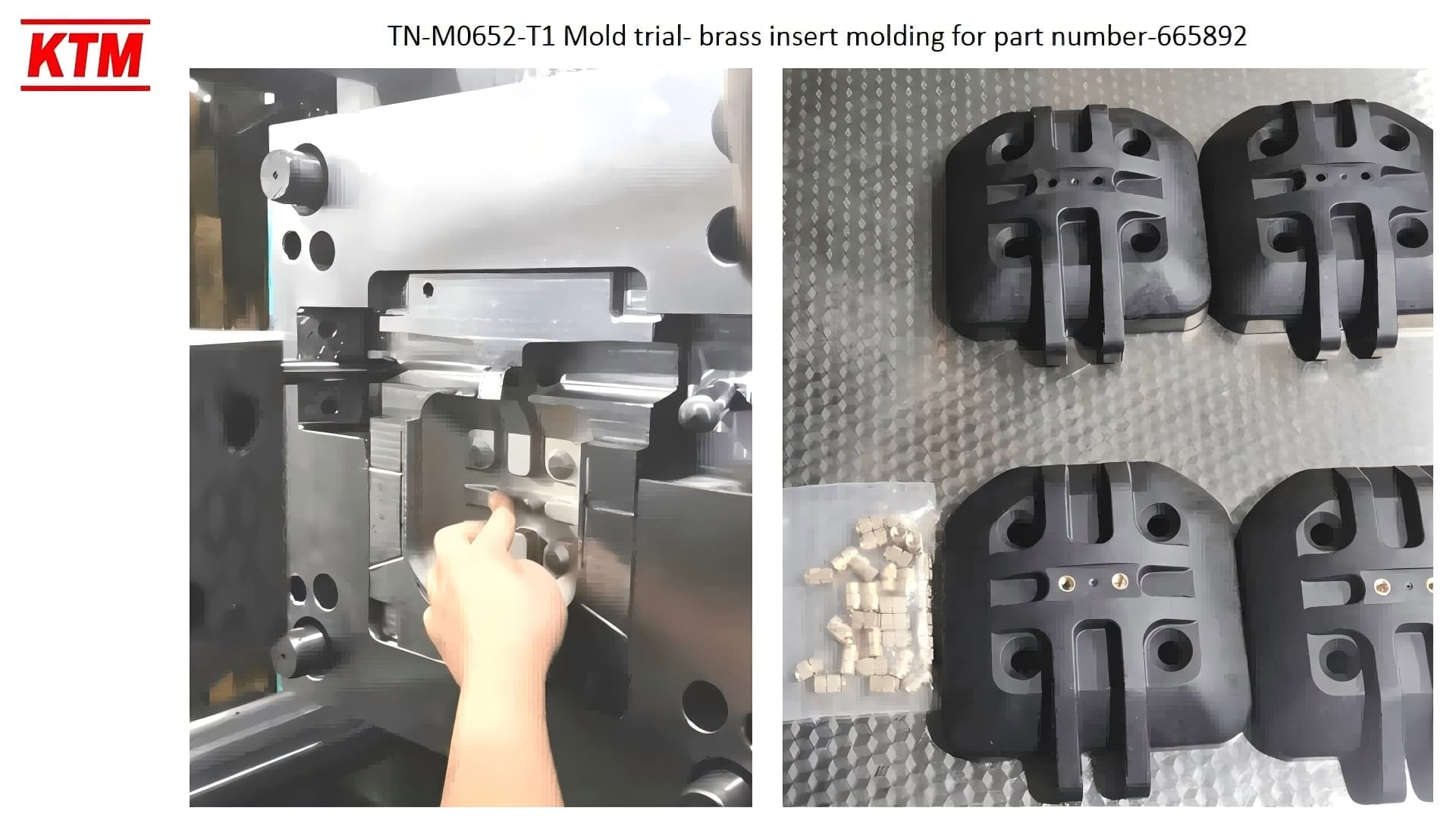
We design the cavity layout, insert pockets, locating features, shut-offs, gates, cooling, and ejection around your part. The DFM review checks how insert tolerances combine with plastic shrinkage and the finished assembly requirements. Steel grade and cavity count are selected against the resin, expected tool life, demand, and cosmetic specification. Tool drawings are reviewed before manufacture.
Two tooling routes, agreed before quoting:
- Export the mold to your facility after agreed trial approval, with the tool specifications and handover documents defined for your intended molding machine.
- Keep the mold at KTM for production, with ownership, maintenance responsibilities, and release arrangements recorded in the tooling agreement.
Tell us the intended production location at RFQ. It affects machine compatibility, spare parts, trial inserts, documentation, and the delivery plan.
3 Insert Molding Production
Our 40 injection molding machines range from 90–400T, with robotic take-out for molded plastic parts. Metal inserts can be loaded manually or automatically; most are loaded manually. Press selection depends on projected area, cavity count, shot size, and processing requirements. Trials establish the insert-loading method, molding conditions, and inspection plan for your part before routine production.
- Use your approved insert supply. We agree incoming checks, sample requirements, and responsibility for nonconforming inserts before scheduling the trial or production run.
- Combine insert and molding supply. We coordinate revisions and fit checks between the insert and tool, then validate retention and critical dimensions on molded samples.
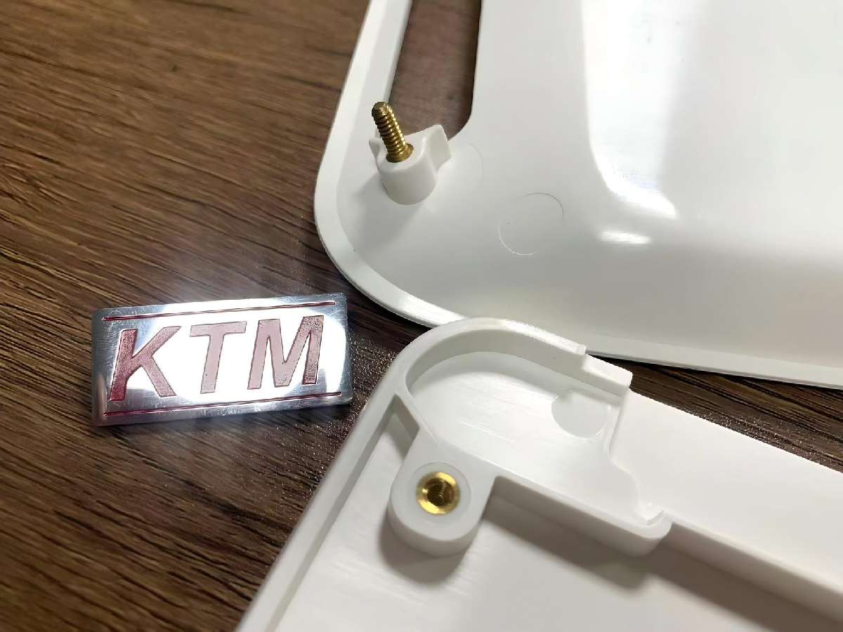
Inspection methods, sampling, material records, and shipment documents are agreed for your project. Specify any thread, pull-out, torque, or electrical test requirements at RFQ.
Custom Insert Molding Solutions for Your Project
Custom insert molding starts with what the metal feature must do: carry fastening loads, locate a moving part, conduct current, or secure an assembly. We review insert geometry, surrounding wall thickness, loading access, gate position, and ejection clearance together. Your drawing and service conditions determine the right combination.
Insert Types and Design Considerations
- Threaded brass inserts—standard or custom bushings for reusable fasteners. Brass insert molding requires thread protection plus retention features designed for axial and rotational loads.
- Stainless pins and shafts—pivots, hinge pins, and locating dowels. Define the exposed datum, corrosion requirement, and resistance to movement within the plastic.
- Custom-machined metal inserts—copper bushings, aluminum brackets, and bronze sleeves to print. We assess locating surfaces, retention geometry, and machining access with the mold design.
- Electrical contacts and terminals—contacts, lead frames, and grounding tabs. Identify exposed contact areas, insulation distances, plating requirements, and any electrical acceptance tests.
- Sensors, magnets, and subassemblies—assessed for molding temperature, pressure, handling, and sealing exposure. Supply the component limits before we confirm whether direct molding is suitable.
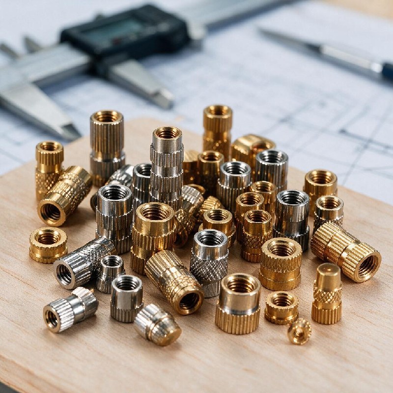
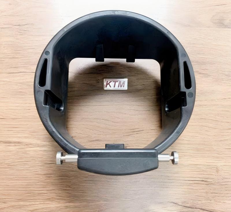
For threaded insert molding and other metal insert molding projects, define pull-out force and resistance to rotation separately. Include the test direction, fixture, temperature, and acceptance limits when these affect function.
Before requesting tooling, identify the insert datums, exposed surfaces, minimum plastic cover, and loading direction. Our engineering review checks these against retention and assembly requirements.
Share the part and insert drawings together so the first review can address their interface. ↓
Review My Part and Insert Drawings →The Insert Molding Process at KTM: 5 Engineering Steps
Each project moves from feasibility review to tooling, trials, and production approval. Optional simulation is scoped separately. The agreed plan identifies the inputs, checks, and approval points needed to release your part.
Step 1 DFM Analysis
The initial review identifies feasibility risks from your part drawing, insert specification, resin, and expected demand. Detailed DFM follows project approval and covers locating datums, retention, shut-offs, gates, vents, wall transitions, and ejection. We flag tolerance conflicts and areas where testing is needed. Drawing revisions and unresolved items are agreed before tool manufacture; the quotation defines the review scope and deliverables.
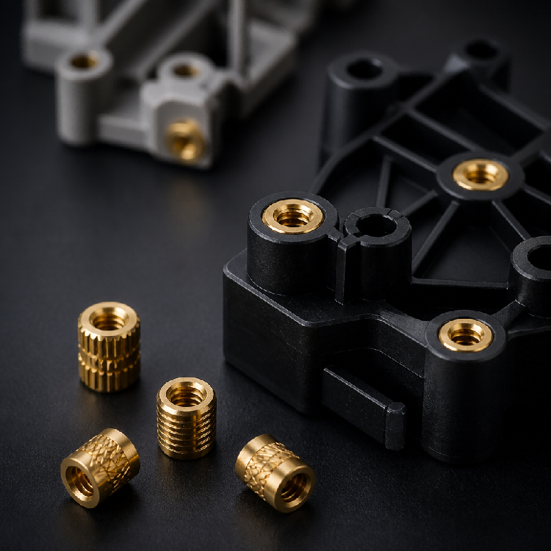
Step 2 Moldflow Simulation (On Request)
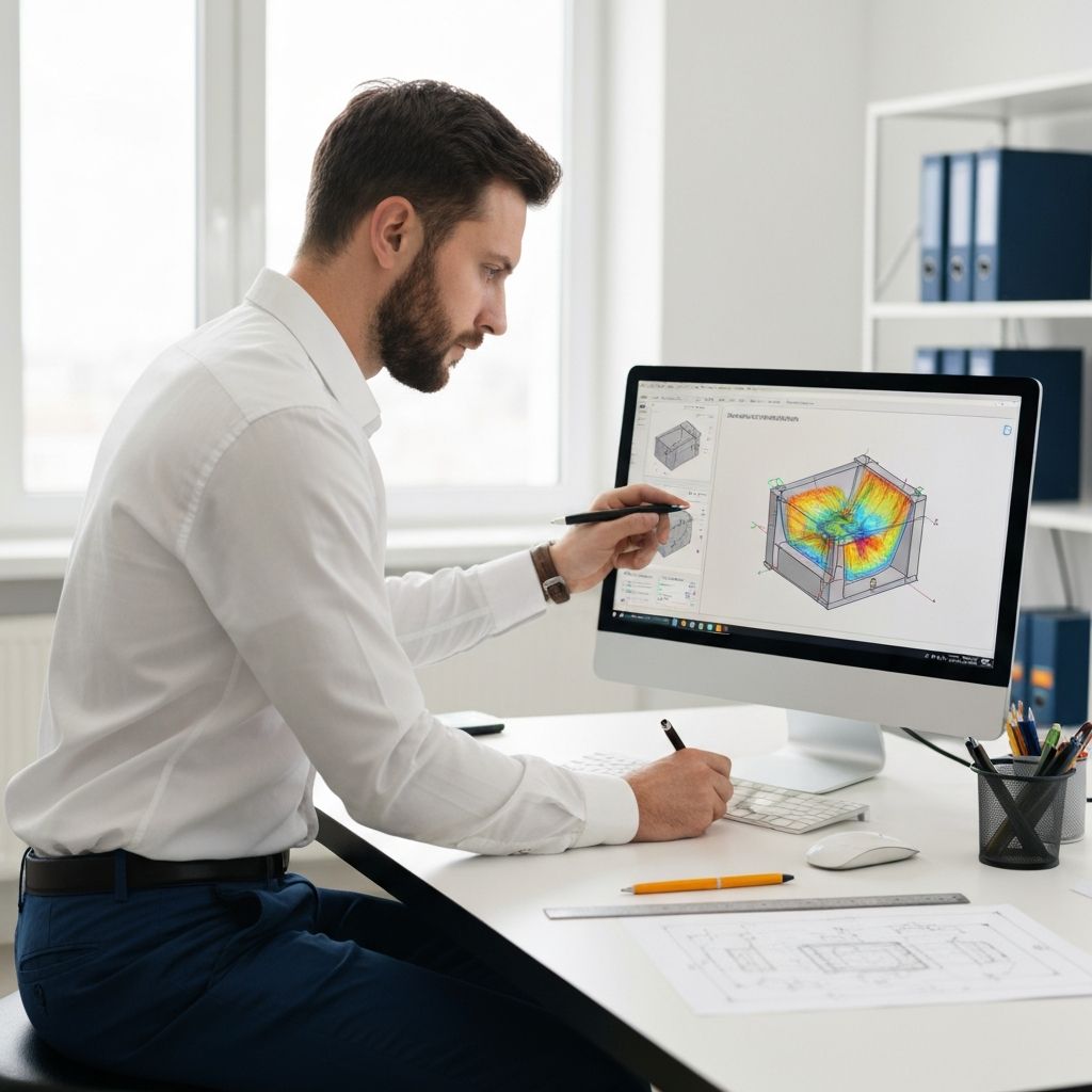
Moldflow is an optional, separately quoted analysis when requested or justified by flow complexity. The agreed study may assess filling, weld lines, pressure, cooling, or warpage. Pressure results can help identify areas needing a closer insert-support review; they do not automatically prove insert movement or retention. The analysis scope, assumptions, fee, and timing are confirmed before work starts, with physical trials used for validation.
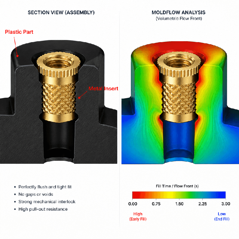
Step 3 Insert Machining + Mold Build in Parallel
Insert machining and mold work can run in parallel once the related drawings are approved. The team checks locating surfaces, pocket fit, shut-offs, and access for loading before the molding trial. Any coating allowance or insert variation must be included in that check. A fit problem is recorded against the relevant drawing revision, with the correction agreed before the tool proceeds to trial.
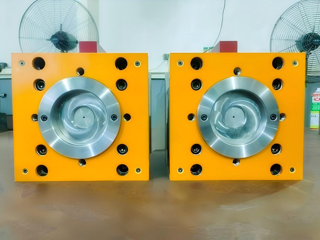
Step 4 Mold Trials and Sample Approval
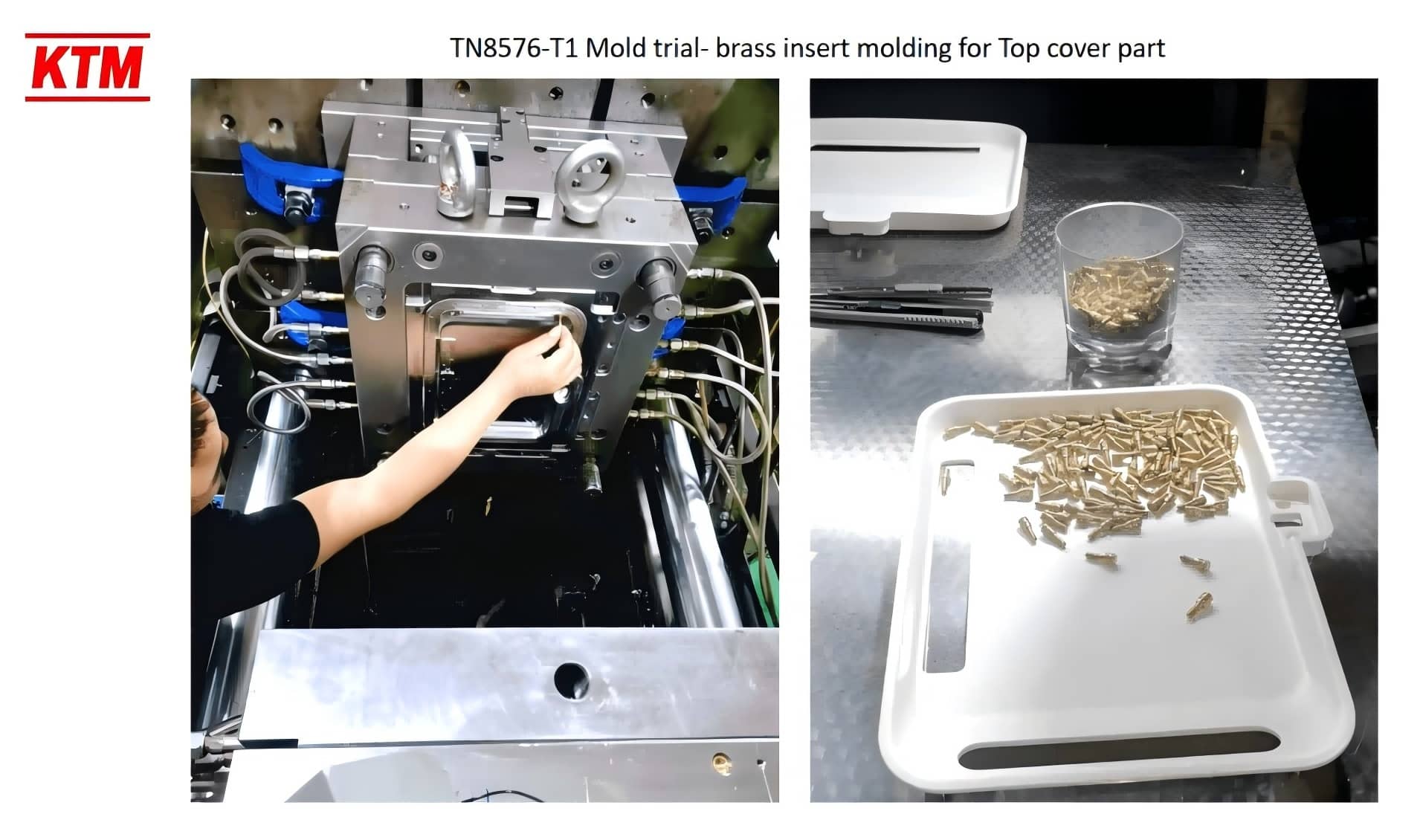
The first trial checks filling, flash, insert position, thread access, ejection, and the agreed critical dimensions. Findings are recorded with the required corrections and follow-up checks. Further trials confirm those changes under the intended production conditions. Approval depends on the agreed acceptance criteria, rather than a fixed number of trial rounds. Trial reports and molding video help your team review the part and process before release.
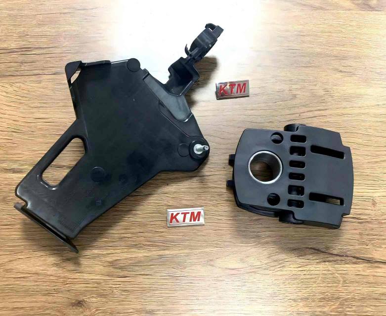
Step 5 Production + QC
Production follows the approved loading method and molding conditions. The quality plan defines incoming checks, first-piece approval, inspection, and shipment records. Verification may include CMM measurements, thread gauges, pull-out force, or rotational resistance. Acceptance limits and sampling are agreed in advance. For repeat orders, drawing revisions, materials, and process changes remain controlled. Agree how any nonconformance will be reported, investigated, and resolved before production starts.
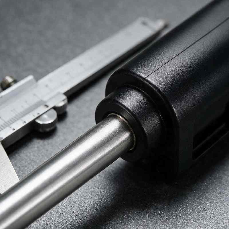
Resin grade and insert alloy influence both tooling decisions and the validation plan. ↓
Materials & Insert Types for Your Project
Select injection molding inserts and resin as a system. Shrinkage, thermal expansion, moisture, service temperature, and applied loads affect fit and retention. These material families are starting points for review; the specific grade, insert finish, and molding conditions determine suitability. Send the intended environment and drawing requirements with your material specification.
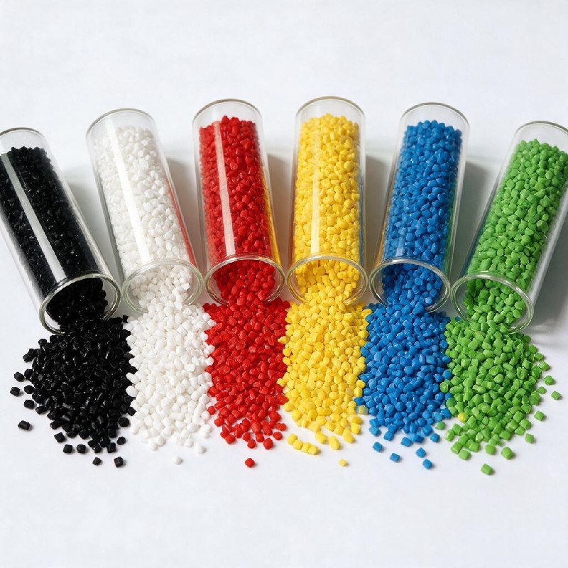
Plastic Resins
| Resin | Common Use Case | Design and Validation Focus |
|---|---|---|
| ABS | Enclosures, housings, consumer parts | Use mechanical retention features; do not assume reliable adhesion to metal. |
| PC | Optical-adjacent housings, lighting | Review stress around inserts, drying, thermal control, and chemical exposure. |
| PC/ABS | Automotive interior trim | Evaluate the selected grade's shrinkage and stress around larger inserts. |
| PA6/PA66 (+30% GF) | Structural brackets, under-hood parts | Account for flow-dependent shrinkage, fiber orientation, and moisture conditioning. |
| POM (Delrin) | Gears, low-friction components | Use suitable knurls, grooves, or undercuts; validate retention under load. |
| PP | Fluid handling, living hinges | Review mechanical retention and creep under sustained load and temperature. |
| PEEK | Medical components, aerospace | Requires suitable high-temperature equipment and tooling; hot runners are optional. |
| TPE/TPU | Grips, seals, gaskets | Adhesion is grade/substrate dependent; assess mechanical retention or surface preparation. |
Insert Materials
| Alloy | Typical Application | Manufacturing and Specification Notes |
|---|---|---|
| Brass | Threaded inserts, bushings | Specify alloy, thread, finish, and retention geometry for each brass molding insert. |
| Stainless 303/304/316 | Pins, shafts, locating dowels | Select alloy for machining and service conditions; 316 alone does not establish medical compliance. |
| Carbon steel, zinc-plated | Structural fasteners, sleeves | Allow for plating thickness on locating and shut-off surfaces; confirm coating requirements. |
| Aluminum 6061/7075 | Brackets, lightweight bodies | Review wall strength, surface finish, and any anodizing allowance before tool fit checks. |
| Copper C110 | Electrical contacts, terminals | Specify conductivity, contact surfaces, and plating; confirm machined or stamped supply. |
| Custom per drawing | Bronze and other specified alloys | Material availability, machining route, and required records are reviewed against your print. |
Send the resin grade, insert alloy, service temperature, and load requirements. If material selection is still open, tell us the function the finished part must meet.
Discuss My Resin and Insert Materials →Why Choose KTM as Your Insert Molding Manufacturer in China
Led by a founder with more than 20 years of experience, KTM brings insert machining, mold building, and molding into one project team. When comparing insert injection molding manufacturers, ask who reviews the interface, how performance will be verified, and what happens if samples fail acceptance. These are responsibilities we agree with you before production.
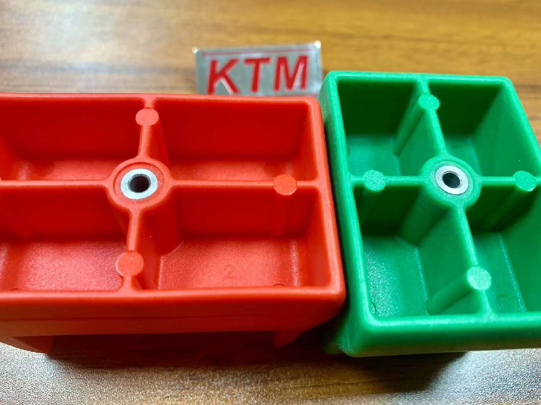
6 Reasons Engineers Choose KTM
1. Insert Fit Reviewed Early
We review locating datums, pocket clearances, and insert variation before machining. Physical fit checks follow manufacture, so loading and shut-off problems can be addressed before molding trials begin.
2. One Coordinated Project Team
Insert machining, mold building, and molding share an engineering review. Changes are checked across the related drawings, so correcting the insert does not introduce a new tooling or assembly problem.
3. Retention Designed for Load
Knurls, grooves, shoulders, and plastic cover are evaluated against the part's function. Axial pull-out and rotational resistance are separate requirements, with test conditions agreed before performance is accepted.
4. Inspection Defined by the Drawing
Critical dimensions and functional checks are identified before production. The quality plan specifies measurement methods, sampling, acceptance limits, and records, allowing your team to review what is being verified.
5. Engineering Through Tool Approval
Our engineering team reviews tooling decisions and trial findings with your requirements in view. Open issues are tracked through correction and sample approval before the part is released for production.
6. Ownership and Scope in Writing
NDA requirements, tooling ownership, production location, and included documents are agreed before work proceeds. Scope changes receive a written cost and schedule review before you authorize the revised work.
4 Insert Molding Applications and What to Validate
These application examples show the design and validation questions behind different metal–plastic parts. Use them to identify what your drawing and test specification need to define. Your resin grade, insert geometry, service loads, and acceptance criteria determine the final solution.
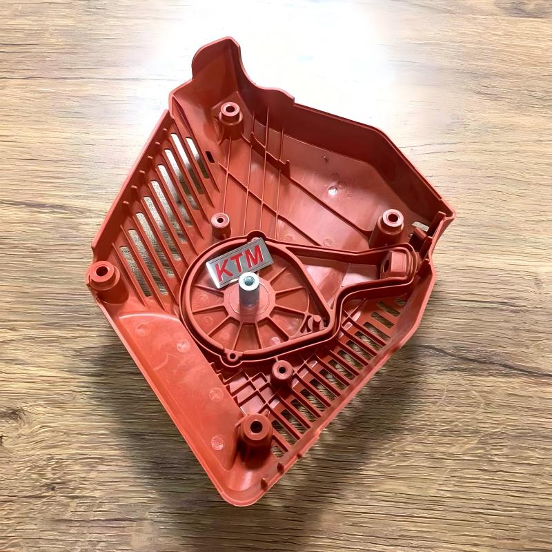
Application 1—Automotive Interior Mechanism
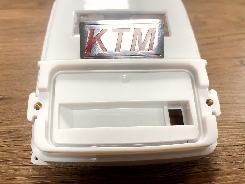
Application 2—Electronics Housing with Threaded Inserts
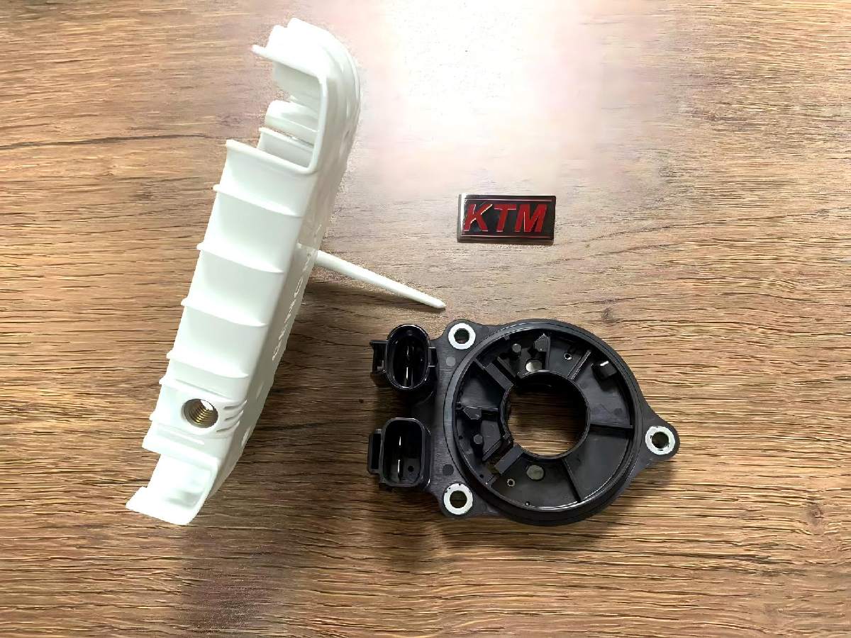
Application 3—Industrial Sensor Enclosure
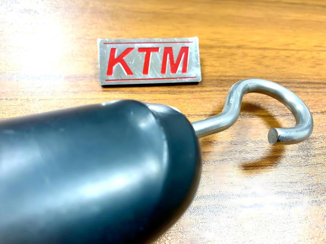
Application 4—Household Hardware with Metal Fasteners
Insert Molding Cost: A Quote You Can Compare
Your quote separates tooling, insert supply, resin and molding, secondary operations, and agreed inspection or documentation. Cavity count, insert loading, wall thickness, cooling, and scrap allowance affect unit cost. A molding cycle might be 32, 45, or 60 seconds on different products; these are examples, not a promised range. Size alone does not determine the cycle, which must be established for your part.
Compare quotations using the same drawing revision, material grade, order assumptions, acceptance tests, and delivery terms. Any scope change receives a written cost and schedule review before work proceeds. The agreed quotation defines included reports, optional analysis, and approval milestones.
Ask for the documentation scope alongside the price so your quality team can review both. ↓
Engineering Documents for Your Insert Molding Project
Agree the documentation package with your engineering and quality teams before placing the order. The four categories below cover design review, trials, dimensional and material records, and optional simulation. Required content, sampling, timing, and fees belong in the quotation or quality plan; an ordinary inspection report does not establish regulatory approval or a complete PPAP submission.
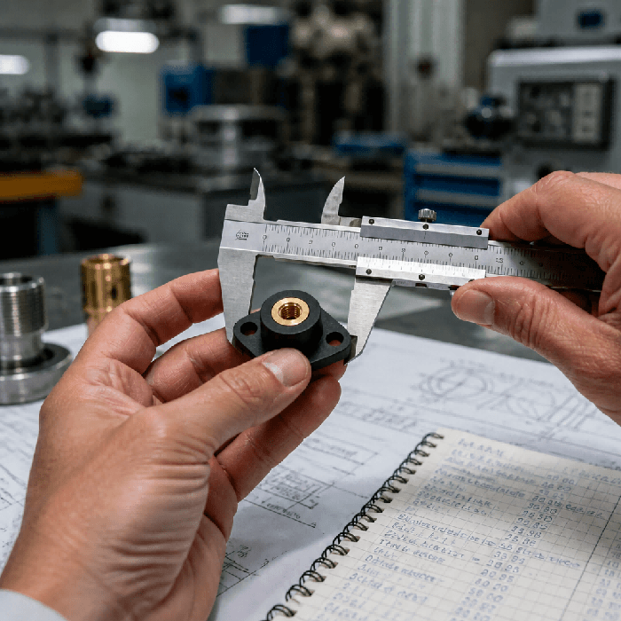
1. Detailed DFM Review Report
Covers insert location, retention, shut-offs, draft, wall transitions, gates, venting, and ejection. The detailed review follows project approval and precedes tool manufacture. Drawing revisions, open questions, and required customer decisions are recorded so the design basis is clear before machining starts.
2. Mold Trial Report and Video
Records trial conditions, observed defects, insert fit, and agreed dimensional or functional results. Corrections and follow-up checks are tied to the relevant trial and drawing revision. Molding video helps your team review loading, molding, and ejection alongside the measured sample results.
3. Inspection and Material Records
Documents critical dimensions and specified checks under the agreed quality plan. CMM measurements, thread gauges, retention tests, and material records are included as scoped. Confirm sampling, traceability, certificate requirements, and any customer-specific submission format before quotation so the necessary records can be planned.
4. Optional Moldflow Analysis
Reports the agreed filling, pressure, cooling, or warpage study with its inputs and assumptions. The simulation supports design decisions and identifies risks to check at trial. Scope, timing, and fees are approved separately; the report does not replace physical dimensional or retention testing.
An initial manufacturability review supports quotation. Detailed DFM follows project approval. Included trial and inspection documents are specified in the quote; optional Moldflow analysis is priced separately before it starts.
The questions below address the remaining decisions before you send an RFQ. ↓
Insert Molding FAQs: Engineer-to-Engineer Answers
Insert molding cost is quoted against the agreed scope:
- Tooling—cavity count, loading features, steel, cooling, and runner system.
- Insert supply—alloy, geometry, tolerance, thread, coating, and sourcing route.
- Molding—resin grade, loading method, cycle, expected yield, and order schedule.
- Validation—required trials, inspection records, functional tests, and optional Moldflow.
- Delivery scope—secondary work, packing, transport terms, and any export-tool requirements.
The quotation states inclusions and assumptions. If a drawing, material, test requirement, or other scope item changes, the revised cost and timing are submitted for your approval before changed work starts. There is no universal savings percentage or cycle time for custom parts.
Either route can work. Tell your insert molding supplier which party will supply the inserts and who will approve incoming quality before the trial is scheduled.
| KTM-Supplied Inserts | Customer-Supplied Inserts |
|---|---|
| Machining and sourcing scoped against the insert drawing | Approved drawings and representative samples supplied by you |
| Insert and mold dimensions reviewed together | Incoming inspection and tool fit checks agreed before trials |
| One team coordinates insert and molding changes | Your existing insert vendor can remain in place |
Tool ownership, payment milestones, maintenance, and release terms are documented in the tooling agreement. Choose the intended production location before tool design:
| Export to Your Facility | Retain at KTM |
|---|---|
| Release after agreed sample approval and contractual milestones | Run production with the agreed maintenance and quality plan |
| Confirm machine interface, handover records, and trial inserts | Agree order releases, tooling care, and shipment records |
For a useful first review, include the insert specification and the function the molded assembly must meet. ↓
Get Your Insert Molding Project Reviewed
Send a PDF drawing or a ZIP package containing your CAD files. Include the insert drawing or part number, resin grade if known, critical tolerances, expected quantities, and target delivery date. Tell us whether you need an export mold or production at KTM. We will review feasibility, flag missing information, and define the quotation scope.
- Need an NDA? Request it before sending confidential files.
- Identify thread, pull-out, torque, or electrical test requirements.
- Initial review for quotation; detailed DFM after project approval.
- Agree tooling ownership, deliverables, and timing in writing.