Custom Injection Mold Components — Sliders, Lifters & Mold Inserts
Made to your drawings for new tools and replacement parts. KTM machines sliders, lifters, mold bases and core/cavity inserts, with engineering review of the fits, wear surfaces and inspection requirements that matter to your mold.
- ±0.005–0.01mm targets on agreed critical features
- Dimensional reports, steel certificates and specified hardness checks
- HASCO / DME / LKM interfaces checked against your specified series
- NDA available before review; documented quality issue assessment
- Typical 10–30 day lead time after drawing approval; single pieces accepted
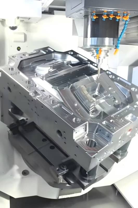
Custom Injection Mold Sliders
An injection mold slider, also called a slide or side-action, forms features that cannot release along the main mold-opening direction. Side holes, outer snap features and undercut ribs often need a slider to withdraw before ejection. We machine the slider body and related wear components to your approved assembly drawings.
A pin-driven assembly commonly includes a slider body, angled pin, guide rail, wedge lock and wear plate. Hydraulic and other drive arrangements require different interfaces. For a replacement injection molding slider, include the pocket, heel-block contact, guide fits and shut-off datums. A worn sample alone may not reveal the original clearance or geometry.
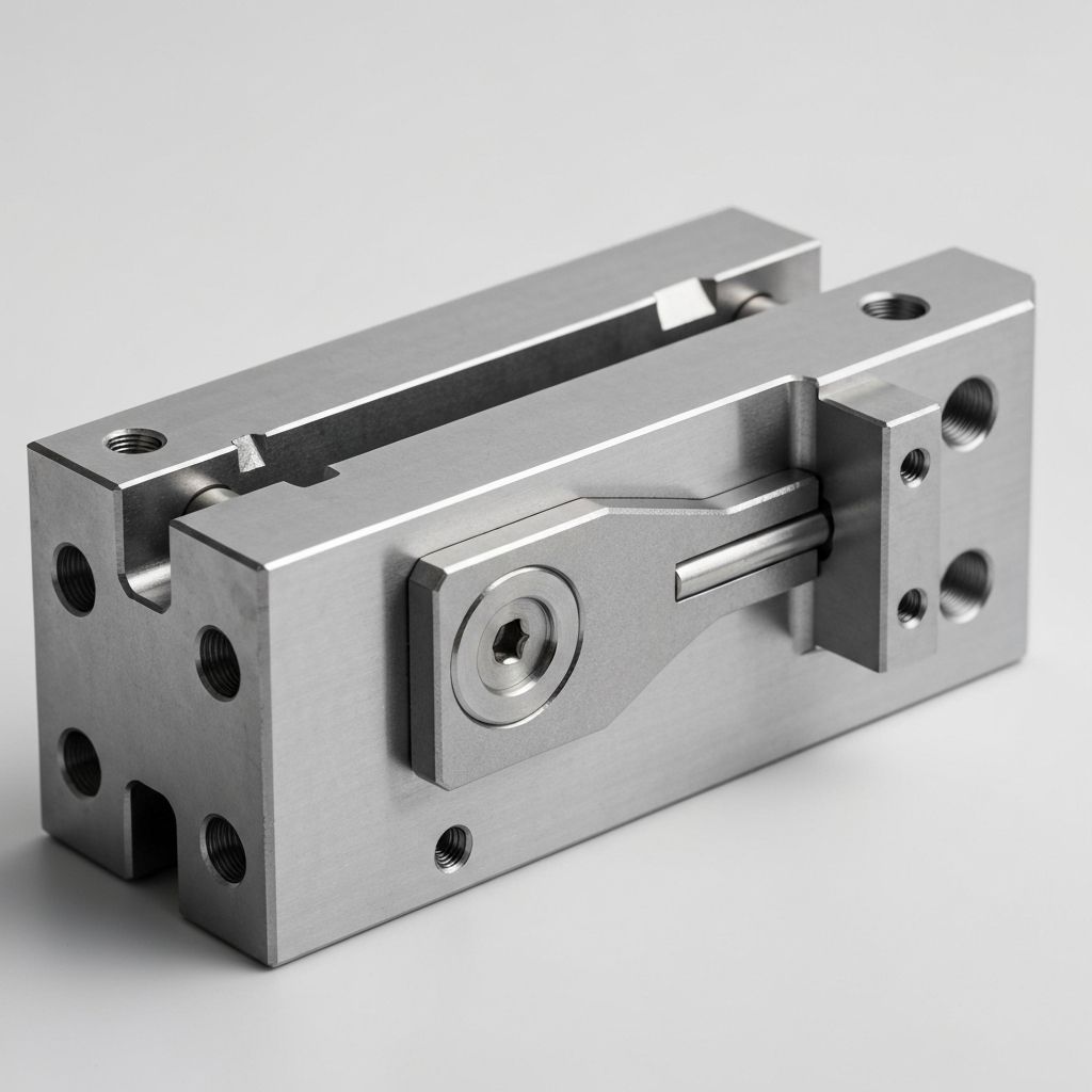
How a Slider Works in Injection Molding
In a typical pin-driven system, opening the mold moves the angled pin relative to the slider, driving it sideways until the undercut clears. A suitable retainer keeps the slider in its open position during ejection. During closing, the pin returns the slider and the wedge lock seats against its back. Hydraulic systems use a separately controlled motion sequence.
The locking faces carry the injection load; the angled pin should not be treated as the primary pressure lock. Drawing review therefore covers projected cavity force, lock contact, guide support and release travel. We also check shut-off geometry, steel condition and wear-surface requirements. Cycle life depends on these details, molding conditions and maintenance, so we avoid a universal shot-count promise.
KTM Custom Slider Capabilities
Your drawing defines the machining and inspection scope. These are the main details we confirm before producing custom sliders:
Materials
H13, SKD61 and 1.2344 for hardened sliders; P20, 718H or NAK80 for prehardened components, selected against your drawing and expected wear conditions.
Tolerances
Critical mating and shut-off surfaces can target ±0.005mm; achievable tolerances depend on component size, geometry, steel condition and specified post-treatment finishing operations.
Surface treatments
Nitriding and polishing follow the approved drawing; specify hardness, case depth, finish grade and any coating before we agree the machining route.
Compatibility
Send the HASCO, DME or LKM series and mating dimensions; we check pocket geometry, mounting details and thermal clearances before machining starts.
Lead time
Typical lead time is 10–30 days after drawing approval; steel availability, treatment, finishing and quantity determine the project delivery date we confirm.
Before machining, our engineers review tolerance stack-up, mating datums, release clearance and the specified heat-treatment route. The agreed inspection plan identifies which features need CMM measurement, gauges or surface checks. Shipment documentation includes dimensional results, material certificates and the specified hardness verification, so your team can compare the component with the approved drawing.
Slider vs Lifter — Which One Do You Need?
Start with the undercut location and the available release motion. These are typical arrangements; the complete mold layout determines the final choice.
| Feature | Slider | Lifter |
|---|---|---|
| Undercut location | Often external; depends on mold layout | Often internal; depends on release direction |
| Motion direction | Sideways relative to mold opening | Ejection plus lateral release |
| Driven by | Angled pin or hydraulic cylinder | Ejector plate and guided angled lifter |
| Typical use | Side holes, snap features, ribs on outer wall | Internal snap ribs and local undercut recesses |
| Key space requirement | Opening travel and room for the side-action | Ejector stroke and guided base travel |
A part may need both systems. Full internal threads can require unscrewing or a collapsible core rather than an ordinary lifter. If you also need the complete injection mold, include the part model and assembly layout so the component interfaces can be reviewed together.
Common Slider Issues We Resolve
For a replacement slider, describe the symptom and operating conditions. The same symptom can have several causes:
- •
Binding or galling — check guide alignment, clearance, surface condition, lubrication and the return or retention mechanism before changing the wear plate.
- •
Flash at the shut-off — examine lock seating, contact area, deflection and worn shut-off surfaces. Cavity pressure and the support arrangement help identify the required correction.
- •
Premature wear — review the steel pair, core hardness, surface treatment and molding temperature. Nitriding is specified by the application, with case depth and surface hardness defined separately.
Send photos, measured wear and the current drawing revision with your inquiry. These details help us separate a component machining issue from assembly or process conditions and define a replacement that addresses the observed problem.
Custom Injection Mold Lifters
A mold lifter releases local undercuts while the part is ejected. Its guided angle combines upward ejection with sideways clearance, often freeing internal snap ribs or inward-facing recesses. We machine custom injection molding lifter components to your drawing, with attention to the forming tip, rod guidance and sliding-base fit.
An injection mold lifter may have an integral forming tip and rod, or a separate tip attached to the rod. The ejector plate drives the assembly through its guide and sliding base. Specify which parts you need, the working angle, available stroke and mating dimensions. Full internal threads usually need a different release mechanism, such as unscrewing or a collapsible core.
Typical lifter applications include:
- Internal snap ribs that lock the part if not released
- Inward-facing hooks with a clear lateral release path
- Local undercut recesses on the part’s inner surface
- Internal features that straight ejector pins cannot release

Lifter Angle, Travel & Support Checks
Release Travel
Calculate lateral clearance from undercut depth and the available ejector stroke; include release allowance, part draft and nearby feature clearance.
Guidance & Return
Match rod support, guide fit and sliding-base travel to the selected angle; verify the return path and ejector-system clearance together.
Shut-off & Cooling
Review shut-off contact, wear surfaces and heat extraction together; surface finish and clearance must suit the steel and molding temperature.
Travel check: For a simple planar lifter, lateral release is approximately ejector stroke × tan(α), where α is measured from the ejection direction. Required stroke is therefore at least (undercut depth + required release clearance) ÷ tan(α). This is a starting geometry check, not a complete design calculation. Confirm interference, part retention, guidance and the return sequence in the assembly.
A larger angle reduces the stroke needed for the same lateral release, but increases guidance demands. Shut-off angle, guide material, clearance and cooling must suit the specific assembly. A single minimum angle or fixed clearance is not appropriate for every mold lifter.
KTM Custom Lifter Capabilities
Send the lifter drawing together with the guide and ejector assembly details. We confirm the forming-tip dimensions, critical fits, steel, treatment and inspection points before machining. For a worn or broken lifter without an original print, include the sample and available mating measurements; replacement geometry needs your approval before manufacture.
Custom Injection Mold Bases
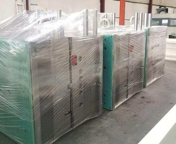
A mold base is the steel-plate assembly that supports and aligns the core/cavity inserts, guide elements and ejector system. Its plate flatness, pocket locations and guide alignment affect the entire tool. KTM machines a custom injection mold base to your approved layout, including specified insert pockets, mounting holes and cooling connections for a new build or replacement assembly.
Standard Components of a Mold Base
Typical two-plate assemblies include the top clamp plate, A plate (cavity plate), B plate (core plate), support plate, spacer blocks and rear clamp plate. Ejector and retainer plates, return pins, guide pins and bushings complete the arrangement.
Three-plate layouts add a runner-separation plate and the associated opening sequence. Specify the plate stack, insert retention, guide system and ejector travel; the required configuration follows your mold design.
Mold Base & Insert Steels
Prehardened mold plates and support blocks, subject to drawing requirements.
Prehardened forming inserts requiring polishability, selected to match your specification.
Corrosion-resistant forming inserts, with hardness and finish specified after treatment.
Hardened wear components and forming inserts, tempered to your specification.
Match Your HASCO / DME / LKM Series
- Specified Series: Provide the supplier, series, frame size and revision. HASCO, DME and LKM dimensions are not automatically interchangeable across systems.
- Machining Scope: Define pocket datums, guide and return-pin bores, ejector clearances, mounting holes and cooling connections. We machine the features included in your approved drawing.
- Fit Verification: For an existing tool, include actual mating measurements and wear conditions. Inspection against those agreed dimensions reduces fitting uncertainty at assembly.
KTM Custom Mold Base Capabilities
Structural plates and forming inserts have different material duties. Final steel grade, supply condition and treatment follow the approved specification. We agree inspection points for plate parallelism, pocket position and guide alignment, and confirm the delivery date after reviewing frame size and machining scope.
Other Mold Components We Manufacture
Beyond sliders, lifters and mold bases, we machine plastic injection mold components to your drawings. Specify each component’s mating features, steel condition and inspection requirements. For CNC-machined mold plates, pockets and related fixtures, our precision CNC machining service supports the same drawing-defined requirements.
Injection Mold Inserts — Cores & Cavities
Injection mold inserts here are replaceable tool-steel cores and cavities, not metal inserts molded into the plastic part. We machine forming details, shut-off faces and locating features to your approved drawing. H13, SKD61, S136 or prehardened grades are selected by wear, corrosion and finish requirements. Define pocket fits, retention, cooling interfaces and polishing zones. Heat treatment, hardness and critical dimensions are verified against the agreed inspection plan before shipment leaves the workshop.
Custom Ejector Pins & Sleeves
Custom ejector pins, sleeves, blade ejectors and stepped ejectors address geometries that catalog parts cannot match. Specify diameter, working length, head dimensions, anti-rotation features and the fit with the mating bore. H13 or SKD61 and any nitriding are selected to the drawing. Surface hardness and core hardness are separate requirements. Inspection focuses on the specified diameters, straightness and functional lengths, with treatment records included when required by your approved component inspection plan.
Ejector Plates & Retainer Plates
Ejector and retainer plates must match the mold’s pin pattern and guided travel. We machine pin bores, head pockets, return-pin features and support-pillar clearances to your layout. Specify plate thickness, flatness, parallelism, hole position and the datum used to locate each feature. These details help control assembly alignment and reduce binding. For a replacement plate, provide the existing pin layout and actual mating dimensions as well as the approved drawing and revision.
Guide Pins & Bushings
Guide pins, leader pins and bushings align the mold plates or moving components. We machine nonstandard lengths, shoulders and mounting details to your drawing, then finish the mating surfaces to the specified fit. Steel or bronze selection depends on load, temperature, lubrication and the guide arrangement. Specify hardness, finish and any treatment rather than assuming one coating suits every tool. Inspection covers the relevant diameters, locating features and functional lengths before shipment.
Assembly & Inspection Fixtures: Custom locating jigs, drilling fixtures and checking fixtures support mold building and component qualification. Specify the reference datums, locating points and inspection access so repeated setups check the same functional features. Fixture scope and acceptance criteria are agreed from your drawings.
Why Engineering Teams Choose KTM for Mold Components
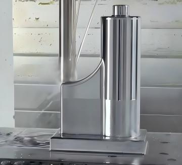
Fit Checked Against Your Tool
A correct nominal size is only part of a reliable replacement. We review the pocket, guide fits, shut-off contacts and datum scheme against your assembly drawing. For HASCO, DME or LKM tooling, the exact supplier series and mating dimensions define compatibility. Agreed inspection points make the fit requirements visible before machining, helping your team plan assembly with fewer avoidable surprises.
Supplier Series & Mating Dimensions Checked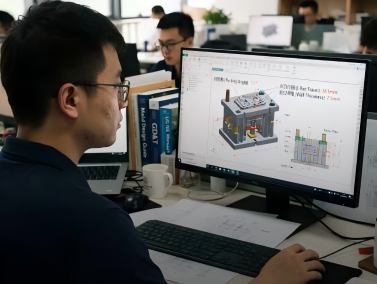
Engineering Review Before Machining
Our engineers review the component drawing for machining access, critical fits, release travel and treatment requirements. Slider locking faces and lifter guidance receive particular attention because wear or deflection can affect part quality. Any proposed drawing change needs your approval before manufacture. The aim is a clear machining specification and inspection plan, rather than an unqualified promise about tool life.
Senior-Engineer Drawing Review
One Piece or Full Set, Same Standard
A single replacement lifter and a set of custom mold components receive the same drawing-based review. We confirm steel grade, treatment, critical dimensions and required inspection documents before production. Material certificates and dimensional results support incoming checks. For repeat orders, identify the approved revision and any changes to the mating tool so each replacement is checked against your current requirements.
Inspection Documents, Single Pieces AcceptedBacked by 20 Years of Mold Engineering
Inside Our Workshop
KTM’s Dongguan workshop uses Fanuc CNC machining centers and Sodick mirror EDM, supported by milling, grinding and drilling. Inspection equipment includes CMM, 2D projection, pin and plug gauges, micrometers, calipers, height gauges and hardness testers. Measurements follow the approved component inspection plan. For customers who need tool trials or production at KTM, our 90–600T molding machines support custom injection molding. Trial scope and assembly validation are quoted separately from individual component machining.
Mold Engineering Experience
KTM was founded by a mold-design specialist with 20+ years of practical mold engineering experience. That background informs how our team reviews component drawings: a slider needs adequate locking support, a lifter needs a complete release path, and an insert needs defined locating datums. We raise unclear fits, treatment requirements or inspection points before cutting steel. This gives your engineer a documented specification to approve and your purchasing team a clear basis for comparing the quote.
Customers Who Stay
Some customers in the United States, Europe and Mexico have worked with KTM for 10–15 years on tooling and replacement components. Repeat component work depends on more than retaining a file. Each order needs the correct drawing revision, steel condition, treatment and inspection requirements. We ask customers to identify changes to the original mold or mating pocket before a replacement is made, so an archived drawing does not conceal a changed fit or service condition.
Injection Mold Components: Buyer FAQs
What information do you need to quote custom injection mold components?
Send the component drawing, quantity, material and required delivery date. Include a 2D PDF with units, revision, tolerances, datums, hardness and surface finish. A STEP, IGES or X_T model helps clarify complex geometry; send 3D CAD by email. For a slider or lifter, include the relevant assembly and mating dimensions. We provide a first response within 24 hours, then confirm any missing details before issuing the final quotation.
Can you make one replacement component for an existing mold?
Yes. We accept single-piece orders for replacement sliders, lifters, inserts and other custom components. Supply the latest approved drawing and the actual mating measurements, especially if the original part or pocket is worn. A sample can support review, but wear may conceal the intended clearance. Any reconstructed geometry must be agreed before machining. Quantity, steel, treatment and inspection scope determine the quotation.
What is the difference between a slider and a lifter in injection molding?
A slider usually withdraws sideways during mold opening to release side holes or external undercuts. A lifter combines ejection with lateral movement and often releases internal snap ribs or local recesses. The available travel, undercut location and mold layout determine the choice. Full internal threads may need unscrewing or a collapsible core. Send the part and assembly drawings if the release direction is unclear.
Are your injection mold inserts tooling inserts or molded-in metal inserts?
This service covers replaceable core and cavity inserts that form the plastic part inside the tool. We machine their forming geometry, locating features and interfaces to your drawing. Metal inserts encapsulated within a plastic part belong to insert molding, which is a different requirement. Tell us which type you need so we can review the correct tooling or molding scope.
Can you match HASCO, DME or LKM mold base dimensions?
We can machine to the specified supplier series and your approved drawings. Provide the exact frame size, plate layout, pocket datums, guide system and mounting details. Components from different brands or series are not automatically interchangeable. For an existing tool, actual mating dimensions help confirm the required fits. Compatibility is assessed against the agreed assembly dimensions rather than a general brand-name guarantee.
Which steels, hardness levels and surface treatments can you supply?
Common grades include P20, 1.2738, 718H, NAK80, S136, H13, SKD61 and 1.2344. Plate support, forming surfaces and wear components have different duties. Prehardened grades and heat-treated steels therefore need different specifications. Define the steel, final hardness, nitriding case requirements and polishing zones on the drawing. We confirm availability and treatment scope at quotation; material certificates and specified hardness checks support shipment acceptance.
What tolerances and inspection documents will I receive?
Critical features can target ±0.005–0.01mm, subject to geometry, size, material condition and finishing after treatment. We confirm achievable tolerances before accepting the drawing. Dimensional results identify the agreed critical features and inspection methods, using CMM or suitable gauges as appropriate. Shipment documentation includes material certificates and specified hardness verification. Tell us if your incoming inspection needs a particular report format or additional measurements.
What is the lead time, and when will you reply to my inquiry?
Our first response is within 24 hours. Typical manufacturing lead time is 10–30 days after drawing approval, depending on complexity, steel availability, heat treatment, finishing and quantity. We confirm a project-specific delivery date in the quotation. Final pricing may require more time when drawings or specifications are incomplete. If your mold is down, include the required arrival date so we can assess an urgent schedule.
Is there a minimum order quantity, and what affects price?
There is no minimum order quantity. We quote single replacements, prototypes and complete component sets. Price depends on steel and stock size, geometry, machining and EDM work, heat treatment, polishing, inspection scope and quantity. A small order still needs setup and verification, so the unit price may differ from a repeat batch. The quotation identifies the agreed scope and delivery terms.
How are confidential drawings and repeat-order revisions handled?
Request an NDA before sending confidential drawings. We retain approved specifications for repeat work, but ask you to identify the current revision and changes to the mating mold. A repeated order is reviewed against those requirements before production. Your component drawings are used for your project; they are not offered as another customer’s design. Any scope change is confirmed before machining begins.
What happens if a component does not meet the approved drawing?
Send the order reference, drawing revision, photos and inspection results showing the affected features. Our engineering team compares the evidence with the approved specification and reviews measurement or assembly conditions where relevant. If a manufacturing nonconformance is confirmed, we agree the appropriate repair or replacement route under the order terms. We provide a first response within 24 hours; the resolution schedule depends on the confirmed corrective work.
How We Protect Your Project

Confidential Drawings
Request an NDA before sharing confidential component drawings. Approved designs are used for your project, with access limited to the work required for review, machining and inspection, rather than another customer’s product.
Transparent Pricing
Your quote identifies steel, machining, treatment, inspection and delivery scope. Pricing remains as quoted when the approved drawings and specifications stay unchanged; any proposed scope change is reviewed and confirmed before work.

Records on File
We retain approved component specifications for repeat orders. Identify the drawing revision and any changes to the mating tool; this lets us review the replacement fit instead of assuming dimensions remain valid.
Quality Backed in Writing
If inspection reveals a mismatch, send photos and measured results. Our engineers compare them with the approved drawing and agree repair or replacement for confirmed manufacturing nonconformance, following the order’s agreed terms.
Send Your Mold Component Drawings
Need a replacement slider, a custom lifter or a set of injection mold components for a new tool? Send your drawings and mating requirements. Our engineering team provides a first response within 24 hours, identifies any missing specifications and confirms the machining, inspection and delivery scope before the final quotation.
Help us review the right details: Use the form’s file upload for a 2D PDF. Email STEP, IGES or X_T models to inquiry@ktm-mold.com. Include drawing units and revision, quantity, steel and hardness, critical datums and fits, surface finish and your required arrival date. For replacements, add the mating pocket dimensions and a brief description of the wear or failure.
Other Ways to Reach Us
For related die-casting tooling, include the tool type and component drawing so we can review the correct material and machining scope. Explore die casting mold work →