Injection Molding: How the Process Works from Design to Production
September 24, 2026 by Henry Zeng
What is injection molding?
Plastic injection molding melts thermoplastic resin, injects it into an injection mold, then cools and ejects the part. Once you have approved the design, material and process, the same mold can make repeat parts. In British English, the process is also spelled injection moulding.
For typical KTM parts, a molding cycle takes about 30 to 90 seconds, depending on the part's structure. Before repeat production, your project still needs drawing review, material selection, toolmaking, trials, sample inspection and approval.
The process is commonly used for housings, covers, clips and other plastic parts made repeatedly from an approved design. The mold is an upfront investment, so your expected volume matters. If the design is still changing, a prototype or low-volume injection molding route may be worth comparing before you commit to production tooling.
What the machine and mold do
The machine prepares and injects the resin. The mold shapes and cools it.
- The hopper holds the resin before processing. Some materials need controlled drying or storage, so the resin grade and application requirements belong in the project request.
- The heated barrel melts the resin. A screw conveys and mixes it, then injects a measured amount called a shot into the mold.
- The clamping unit closes the mold and holds its two halves together while the cavity fills. The required clamping capacity depends on factors such as projected part area, cavity arrangement and process conditions.
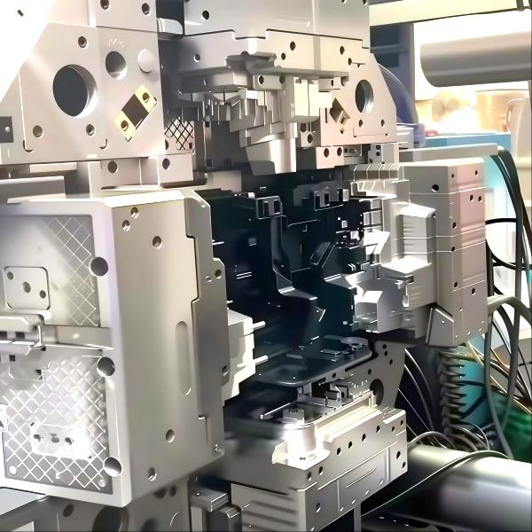
- The mold contains the cavity and core that form your part. It also includes a gate and runner system that guides the melt, cooling channels that remove heat, and an ejection system that releases the part after cooling.
- The gate is the opening where material enters your part. Its position can affect weld lines, appearance, filling balance and where a gate mark remains.
- The cooling system removes heat from the mold and part. Cooling layout and cooling time affect cycle efficiency, shrinkage and dimensional stability.
Before toolmaking, check the proposed gate, parting line, ejection and cooling against your drawing. Changes get harder once steel is cut.
KTM runs about 40 Haitian, LOG and FANUC injection molding machines from 90T to 400T. Partner plants handle molding above 400T.
For tooling, KTM has CNC machining with up to 2,300 mm of travel and SODICK EDM, and builds molds up to about 2,000 mm in size and 15 tonnes in weight. Parts are checked on a CMM, with a profile projector, hardness tester and hand gauges for the rest.
The overmolding services page covers tooling for two-material parts. Ask which equipment and inspection steps apply to your part.
Types of injection molding
Choose the molding route around what your part must do. KTM has a service page for each option below.
| Route with a KTM service page | When to consider it | Design question to settle |
|---|---|---|
| Custom thermoplastic injection molding | A repeat plastic part with an agreed material and drawing | Can the geometry fill, cool and release from the proposed tool? |
| Overmolding | A second material or layer over an existing substrate | Will the materials bond, and how will the substrate be held? |
| Insert molding | A molded part around a pre-positioned insert | Can the insert stay located under molding pressure? |
| Two-shot molding | Two materials or colors made in a coordinated molding sequence | Do the materials, part geometry and tooling sequence fit? |
| Gas-assisted injection molding | A geometry where a gas channel might reduce a heavy solid section | Where can the gas enter and where will the hollow channel run? |
Ask which steps KTM performs directly. Partner plants handle molding above 400T.
Hot-runner molds and unscrewing injection molds are tooling options rather than separate families of plastic. A hot runner changes how melt reaches the cavity; an unscrewing mechanism releases molded threads. Each adds tooling decisions that belong in the DFM review. KTM mainly uses YUDO and Chinese-brand hot runner systems. INCOE and Mold-Masters are used only when a customer specifies the brand.
The repeatable injection molding cycle
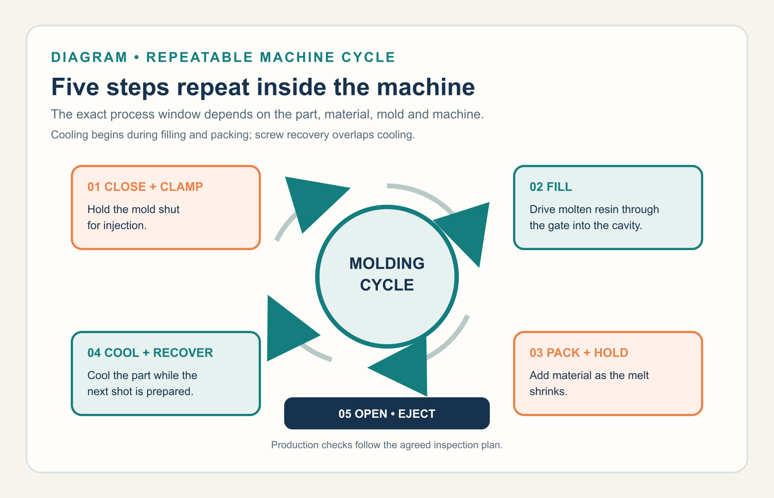
The injection molding process repeats the same sequence for each shot. Temperature, pressure, speed and cycle time depend on the resin, geometry, mold and machine; a setting copied from a different part is not a production specification. Before molding begins, the resin is prepared for its grade. During repeat production, the screw usually prepares the next shot while the previous part cools.
1. Close and clamp the mold
The mold closes, and the clamping unit holds its halves together against the pressure of the incoming melt.
2. Fill the cavity
The screw moves forward and pushes molten resin through the runner and gate into the cavity. The material flows around features such as ribs, bosses and openings. Flow length, wall thickness changes, gate location and venting can influence whether the cavity fills evenly.
Short shots, burn marks, weld lines and trapped air can point to different causes. Part geometry, gate design, venting, resin and process settings may all need review during a trial.
3. Pack and hold the material
Once the cavity is nearly full, holding pressure feeds more melt through an open gate as the polymer shrinks. That helps control part weight and dimensions. With a conventional gate that seals by cooling, the flow stops when the gate freezes.
Cooling starts as soon as the melt touches the mold, including during filling and packing. The named cooling stage is the remaining time the closed mold needs before the part can be ejected.
4. Cool the part and recover the next shot
The part stays in the mold while heat leaves the polymer. The screw can recover and prepare the next shot during part of this time. The part must be firm enough to eject without unacceptable deformation; longer cooling also lengthens the cycle.
Resin, wall thickness, mold layout and cooling design affect this balance. Warpage or changing dimensions after ejection can require a joint review of cooling, shrinkage, geometry and process settings.
5. Open the mold, eject and inspect
The mold opens after the part is ready to leave the tool. Ejector pins, sleeves, a stripper system or another planned mechanism releases it. Parts are removed, and production checks follow the agreed inspection plan.
For trial samples, agree which dimensions will be measured and which sample will define acceptable appearance. Fit, gate marks, flash, warpage, color and functional checks may all matter, depending on your part.
The machine cycle and the project timeline
The machine cycle repeats for every shot. Your project runs from a drawing to an approved part. The last column shows KTM's stages.
| Project stage | Decision you make | Evidence to request or approve | At KTM |
|---|---|---|---|
| Drawing and application review | You define how the part must fit, work and look | 3D model, 2D drawing, resin and application notes | Your project lead contacts you within 24 hours. An engineer reviews the job; a mature design is usually quoted in 1 to 3 days. If it is not ready to quote, you get feedback. |
| Design for manufacturing (DFM) review | You resolve draft, wall changes, parting line, gate and ejection risks | Marked design feedback and agreed changes | KTM's free DFM report checks moldability and structural issues such as undercuts that block release. Detailed mold DFM covers ejector positions, sink, filling and gate location after the tooling order. |
| Mold design and build | You approve the tool concept and key features | Mold layout, gate and ejection details, cooling approach | Simple molds take 4 to 6 weeks; complex structures or high-grade steel needing heat treatment take 6 to 10 weeks. Very large, complex or hot-runner molds take 12 weeks or more. KTM can provide steel and heat-treatment certificates. |
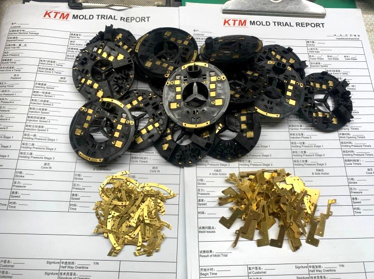
| First trial | You check whether the tool and process produce a usable sample | Trial samples and a recorded list of observations | Within 2 days after T1, KTM sends 5 to 10 samples with a trial video and report. |
| Measurement and correction | You compare the sample with your drawing and acceptance criteria | Measurement results and agreed correction actions | A dimensional report follows, using CMM where required. Expect 1 to 3 modification rounds. A change you request after the trial that needs mold work carries a fee based on the change. |
| Production approval | You release the part for repeat orders | Recorded sample approval and an agreed plan for production checks | The timing depends on how quickly you send feedback. KTM inspects every production part. |
Names vary by supplier. Record the accepted sample, drawing revision and repeat-order checks. KTM's custom injection mold design and build page covers tooling in more detail.
Decisions that change your process outcome
Material and preparation
The resin affects shrinkage, flow, stiffness, impact behavior, surface appearance and processing conditions. Some resins are sensitive to moisture and need controlled drying. You should provide the exact material grade when you have selected one, or describe the mechanical, thermal, chemical and appearance requirements that the material must meet.
The resins KTM runs most are ABS (grade 757 is common), PP, POM, PC, PA6, PA66, glass-filled PA6 and PA66 (10 to 50%), talc-filled PP, PS, HDPE and PC/ABS. TPE, TPU and clear PC are also routine. Their available grades differ, so a resin name alone does not specify the finished part. If the grade is unsettled, describe the part's function and environment, then record the selected grade in the approved drawing or material specification.
Typical guideline: check drying requirements against the resin supplier's grade-specific data sheet, because the material family name alone is not enough. KTM dries material before trial molding. Moisture matters most for hygroscopic resins such as PA, PC and PC/ABS.
Wall thickness, draft and geometry
Large changes in wall thickness can increase the risk of sink marks, warpage or uneven cooling. Draft is the slight taper that helps your part release from the mold. Ribs and bosses can add strength, but their thickness relative to the surrounding wall affects filling, cooling and surface appearance.
You should mark critical walls, mating features, sealing surfaces and cosmetic areas on your drawing. That gives your supplier a practical basis for DFM feedback and helps you decide which geometry changes are acceptable.
Typical guideline for early design review: keep the nominal wall thickness consistent where the part allows it. The ranges below are starting points for common unfilled grades, not KTM specifications or mold-compensation values. Check the selected grade, flow length and part geometry before fixing dimensions.
| Resin family | Typical starting wall thickness | Typical molding shrinkage |
|---|---|---|
| ABS | about 1.1 to 3.5 mm | 0.4 to 0.9% |
| PP | about 0.9 to 3.8 mm | 1.0 to 2.5% |
| PC | about 1.0 to 3.8 mm | 0.5 to 0.7% |
| PA / nylon (PA66 for shrinkage) | about 0.8 to 2.9 mm | 0.7 to 1.8% |
For many straight-pull faces, start with 1 to 2° of draft. A light texture may call for about 3°, while a deeper texture may need 5° or more; the texture specification and wall depth decide the final angle. Start rib thickness at 40 to 60% of the adjoining nominal wall thickness to reduce sink risk. For comparative shrinkage data, see LyondellBasell's technical note. Confirm the resin grade before tool design and measure trial parts before production approval.
If you are preparing the drawing for tooling, use the pre-tooling DFM guide to check the part details before you request a quote.
For a closer look at choosing the nominal wall, see our injection molding wall thickness guide.
Gate, runner and venting
Your gate location influences flow direction, weld lines, the gate mark and the appearance of the part. The runner system distributes material to the cavity or cavities. Vents let displaced air escape and can reduce air traps and burn marks.
Ask how the proposed gate and parting line affect your visible surfaces and assembly. If a gate mark must be hidden or removed, state that before the mold design is finalized.
Cooling and cavity count
Cooling layout affects cycle balance, shrinkage and warpage. Multiple cavities can increase output per machine cycle, but they also make filling balance, cavity matching and inspection more important. You should compare the expected order pattern with the tooling cost and the level of cavity consistency your product requires.
Most KTM molds have 1 to 4 cavities. KTM has also built a 100-cavity cable tie mold.
Tolerance and finish
Your drawing should separate critical dimensions from reference dimensions. State the function of each tight requirement and identify the datum scheme where needed. For appearance, describe acceptable texture, gloss, color, weld lines, gate marks and flash locations with a sample or clear reference whenever possible.
Typical guideline: the shrinkage ranges in the table above help frame the DFM discussion, but they are not finished-part tolerances. LyondellBasell's technical note says comparative shrinkage values should not be applied directly to an actual tool design. Agree on the resin grade, measurement conditions and critical dimensions, then inspect trial parts before approving the tool or a tight tolerance.
KTM's routine tolerance is ±0.05 mm. Tighter dimensions are reviewed feature by feature, because what a mold can hold also depends on part size, resin and geometry.
KTM commonly finishes molds to SPI A1 and A2 polish, VDI 21 to 36 texture and Mold-Tech MT-11010. Put the finish on your drawing, because texture depth also sets the draft you need.
Advantages and limitations
- Once a tool and process are approved, you can repeat the same geometry without machining each part from a solid block. You still need a plan for inspection and process drift.
- The tool can form details such as ribs, bosses and clips in one molded part. Undercuts, tight cosmetic demands and multiple materials can make the mold more complex.
- The mold is a one-time investment spread over the approved production quantity. If you expect design changes, that investment can become a liability before the tool is paid back.
- Material choice and mold design set practical limits. A part that needs a very thick section, no draft or a critical surface at the gate may need a redesign or another process.
Common defects and fixes
A visible symptom is a starting point, not a diagnosis. Compare a suspect part with the approved sample, drawing and process record before changing settings or steel.
| Symptom | What to check first | Possible corrective direction |
|---|---|---|
| Short shot | Flow path, thin sections, gate, venting and melt conditions | Review fill balance and trapped air before increasing pressure. |
| Sink mark | Thick sections, ribs, packing and gate freeze | Reduce local mass or revisit packing and gate design. |
| Warpage | Wall variation, cooling balance, resin shrinkage and ejection | Compare measurements after cooling; review geometry and cooling layout. |
| Flash | Parting surfaces, shutoffs, clamp and fill/pack conditions | Inspect the tool and process before trimming flash as a routine step. |
| Burn mark or weld line | Air escape and where flow fronts meet | Review venting, gate position and the part's functional requirements. |
The defects KTM handles most are sink marks, flash, weld lines and warpage. The usual first moves are adjusting cooling time and building custom fixtures.
Where these problems show up at KTM
- PA6 cable ties: filling difficulty and flash.
- Complex PP automotive parts: sink marks.
- Clear PMMA automotive lamp parts: visible weld lines.
- Parts with complex structures: deformation.
How much does injection molding cost?
KTM has no standard mold price list. A mold can cost from a few thousand US dollars to several hundred thousand, depending on the part's structure, cavity count and steel.
Start with two figures: the cost of the mold and the cost of each accepted part. A price without the drawing, resin, quantity and acceptance criteria hides too many assumptions. After the mold and its trials, each order still carries material, machine, labor, inspection and logistics costs.
Roughly in this order, KTM's price drivers are:
- Complex part geometry needs more mold work.
- Cavity count changes the tool and its output per shot.
- Your specified steel affects the tooling price.
- Surface treatment adds finishing work.
- Two-shot and gas-assisted molds need their own design, machines and know-how, so they price differently from standard molds.
- Where the mold goes matters: about 60% of KTM's molds ship out and about 40% stay for production.
- A hot runner adds another tooling choice.
For the mold, ask which steel and expected tool life are priced, how many cavities it has, and whether it needs slides, lifters, unscrewing parts or hot runners. These affect tool cost and maintenance. For each part, compare resin grade, shot weight, cycle time, scrap allowance, secondary operations, checks and packaging. Quotes for the same drawing may assume different tool lives, cavity counts or inspection scopes. Ask each supplier to state its assumptions.
KTM uses S50C (1.1730) for mold bases, and P20, 1.2738, H13 (1.2344), 1.2343 and S136 (1.2316) for cavities and cores. As a general guideline, pre-hardened steels such as P20 suit moderate volumes, hardened H13 suits high volumes and abrasive resins, and stainless S136 suits corrosive resins and mirror polish.
The planning equation is effective cost per accepted part = tool cost / accepted lifetime volume + production cost per accepted part. It compares costs, not selling prices. Reorders, maintenance, trial changes and rejected parts can alter the result. Use a defensible volume forecast and count approved parts, not just shots.
Illustrative example only, not a KTM price or market benchmark: Suppose a hypothetical mold costs $12,000 and production costs $1.20 per accepted part, with no other charges. At 1,000 accepted parts, tool amortization adds $12 per part, for an effective $13.20. At 10,000 accepted parts, it adds $1.20, for an effective $2.40. The example excludes design changes, inspection, shipping, tax and tool maintenance. It shows why volume changes the arithmetic; it does not identify the right volume for your part.
For a KTM quote, send the drawing revision, annual volume and appearance or inspection requirements. Ask whether tooling includes trials, sample measurement, revisions and maintenance so you can compare the same scope across suppliers.
KTM has no minimum order quantity. Small runs carry the trial charge in the unit price, so they cost more per part, and larger runs bring the price down. Unit price depends on resin, part weight, cavity count and cycle time.
Tooling is usually paid 50% up front, 30% after T1 and 20% when the mold is approved for shipment or for production at KTM.
Have a drawing ready? Send your model and drawing for a DFM review. You get a first reply within 24 hours, and a mature design is usually quoted in 1 to 3 days.
What to send for a useful RFQ and DFM review
For a request for quotation (RFQ) and DFM review, send the following when available:
- A 3D model in a commonly usable format, with the revision identified.
- A 2D drawing that shows critical dimensions, tolerances, datums and material information.
- The resin grade, color and any application requirements such as chemical exposure, heat, impact or food contact needs.
- Your expected annual volume, order quantity and likely demand pattern.
- The intended use of the part and the components that it must fit or seal against.
- Surface appearance requirements, texture references and areas where gate marks or parting lines are restricted.
- Your delivery destination and packaging or labeling requirements if they affect the quote.
- Any open design questions that you want the supplier to review before tooling.
KTM's free DFM report checks whether your part can be molded and whether its structure is reasonable, for example undercuts that block release. Ejector positions, sink, filling and gate location are covered in the detailed mold DFM, which KTM provides after the tooling order. Mold flow analysis is done when you ask for it or when the structure is complex, and it is charged.
At KTM, a design change after the first trial that needs mold work carries a modification fee, priced by the change. KTM ships EXW, FOB Shenzhen or DDP, mainly to the US, Canada, the UK, Germany, Spain, France and Poland.
When injection molding is a good fit
Your choice depends on expected volume, revision risk and the cost of the mold. Complex geometry may be feasible, but each added undercut, cavity or cosmetic requirement can change the tool and the quote.
If you are still testing the product or expect frequent geometry changes, compare a prototype or low-volume route with production tooling. Ask for quotes based on your own forecast and revision risk.
KTM's low-volume injection molding page covers runs of roughly 5,000 to 100,000 parts. Below that, KTM has no minimum order quantity, but small runs cost more per part.
KTM points you to 3D printing or vacuum silicone casting when you need only 5 to 50 parts, are still validating the design, cannot yet release the part from a mold, or have modest accuracy requirements. From about 1,000 parts, or at lower volumes with high accuracy requirements, KTM uses steel tooling.
What KTM does not take: KTM does not take aerospace or medical parts that need ISO 13485-level certification, or parts where most dimensions need ±0.005 mm ultra-precision.
Injection molding vs 3D printing vs CNC machining
| Decision | Injection molding | 3D printing | CNC machining |
|---|---|---|---|
| Best use of quantity | Repeat orders after the design is stable and the mold is justified | One-offs, prototypes and iterative geometry | One-offs, prototypes or parts that suit machining |
| Upfront cost | A part-specific mold and trials | Usually no production mold | Programming and setup, but no production mold |
| Unit-cost pattern | Tool cost is spread over accepted parts; production cost remains | Printing time and post-processing remain for each part | Machine time and material removal remain for each part |
| First-piece path | Design review, toolmaking and trials precede an approved molded sample | A build can start from a suitable digital model | Toolpath, stock and fixturing precede a machined sample |
| Material and geometry | Moldable grade; draft, shrinkage, parting line and ejection matter | Depends on the printing process and material | Depends on accessible cutting paths, tool reach and stock material |
| Accuracy decision | Define critical dimensions and inspect samples under agreed conditions | Check process-specific resolution, orientation and post-processing | Check tool access, datum setup and finishing operations |
| Where KTM draws the line | KTM points to steel tooling from about 1,000 parts, or fewer when high accuracy is needed. | KTM points to printing for roughly 5 to 50 parts, early validation or geometry that will not release from a mold when accuracy needs are modest. | Compare machining to the same drawing where a mold or printed part is a poor fit. |
These comparisons do not predict your part's cost or accuracy. Compare quotes to the same drawing, material and acceptance criteria.
Start with your drawing
Collect the model, drawing, material or application requirements, expected quantity and appearance criteria. These let a supplier review moldability and quote the same part that your team intends to approve.
The Dongguan plant covers more than 3,000 m² and has about 80 people, including 8 design engineers and 30 toolmakers. KTM builds roughly 250 to 300 molds a year and more than 4,500 in total, rework not counted.
KTM tells you plainly when a problem comes up and does not add charges mid-project without explaining them.
For production options, see KTM's custom injection molding production page. You can send your drawing through the contact page and ask which material, tooling and sample-approval details are still needed for a quotation.
Written by

Henry Zeng
You may also interested in:
Injection Molding Wall Thickness: Choose a Wall That Can Fill and Perform
Injection molding wall thickness should be thick enough for the selected resin to fill the geometry and for the part to perform, while avoiding unnecessary mass that can cool unevenly