Plastic Part Design for Injection Molding: A Pre-Tooling DFM Guide
September 27, 2026 by Henry Zeng
Plastic part design for injection molding starts before the mold
Plastic part design for injection molding starts with what your product has to do. You then shape the part so it can fill, cool, leave the mold and meet its inspection requirements. A design for manufacturability (DFM) review checks your model alongside the resin, proposed tool and drawing before you authorize tooling. A geometry scan alone cannot tell you whether the molded part will meet that drawing.
When your mold maker says a feature is moldable, ask what that answer assumes about load, fit, appearance and inspection. Leave the review with a marked model, a short list of open items and the revision you both intend to use for tool design.
Start with the part's job and the material requirement
Before you review individual surfaces, write down what your part must do. Include loads, operating temperature, chemical exposure, assembly method, expected production volume and visible faces. Tell your mold maker whether this is a structural support, cover, fluid path, locating part or appearance part. That context tells you which dimensions deserve attention first.
Give the resin grade if you know it. Otherwise, give your heat, load, chemical and appearance requirements. Resin affects flow, shrinkage, cooling and finish. If you change the grade later, revisit the wall, fit and gate decisions that depended on it. Detailed resin selection belongs in its own review.
Name a candidate grade or your limiting requirements. Recheck wall and shrinkage if the grade changes.
An injection molding part design should show your mating parts and say how you will inspect critical features. A snap-fit dimension needs a different review from a reference dimension. Your cosmetic face may need a gate or weld-line decision even when it has no tight dimensional requirement.
Review wall sections, transitions and reinforcement
Check your CAD section views for abrupt wall changes, heavy spots, long thin flow paths and sharp internal corners. A thick spot cools more slowly than the wall beside it and can leave a sink mark on the visible face. A thin path may freeze before the cavity fills. Core out mass where function allows, then check how the change affects stiffness, flow and tooling access.
For a first wall review, keep the nominal thickness as even as your part allows. Where the wall must change, allow a gradual transition with a run of roughly three times the thickness difference (3Δt), where Δt is the thick wall minus the thin wall. For example, a change from 2 mm to 3 mm gives Δt = 1 mm and an initial run of about 3 mm. A large step or visible face may need a longer taper or a cored section; a long flow path can change the gate decision too. Use the ranges below to start the review, then set the actual wall with your resin grade, part geometry and mold maker.
| Resin family | Typical nominal wall, mm | Illustrative mold-shrinkage range | Family-level context |
|---|---|---|---|
| ABS | 1.1-3.5 | 0.4-0.9% | Some ABS grades shrink above the broad 0.4-0.7% amorphous guide; use the selected grade's data. |
| PC | 1.0-3.8 | 0.5-0.7% | Amorphous; check grade and wall before setting tool allowance. |
| PP | 0.9-3.8 | 1.0-2.5% | Semicrystalline; grade, filler and wall thickness move the number. |
| PA/nylon | 0.8-2.9 | 0.7-1.8% for PA66 | Semicrystalline; grade and moisture condition matter. |
| Glass-filled grades | Grade-specific | Check shrinkage along and across flow separately | Fiber direction and the selected grade change both values; use its data sheet. |
Use the shrinkage figures to screen your design, then get the grade data before you set the tool allowance. Glass-filled grades shrink differently along and across the flow direction. Ask for both values and check the likely fiber orientation, especially if a long flow path ends at a critical mating dimension.
Ribs can stiffen your part without thickening the whole wall. At the root of a rib or boss, though, you can still leave enough mass to mark the opposite face. Check the load path, how the feature leaves the mold and which dimension you will inspect.
For a first rib layout, make a rib about 40-60% as thick as the adjoining nominal wall, keep its height no more than about three times its own thickness, and leave at least two wall thicknesses between adjacent ribs. Start the root fillet near 0.25-0.5 times the rib thickness. For a screw boss, try an outside diameter near twice the screw diameter and a boss wall no more than 60% of nominal wall thickness. Core out the boss base and connect it to a sidewall with gussets where the load path allows. You may need different proportions for a heavier load, a larger fastener or a glass-filled grade. If the boss sits behind a visible face, ask your mold maker to check sink risk and tool access before fixing its dimensions.
For your general corners, start the inside radius at least 0.5 times nominal wall thickness and make the outside radius the inside radius plus the wall thickness. That keeps the section closer to uniform around the turn. Increase the radius if your stress or flow requirements call for it, or revise the split and tool access if the corner cannot be molded cleanly.
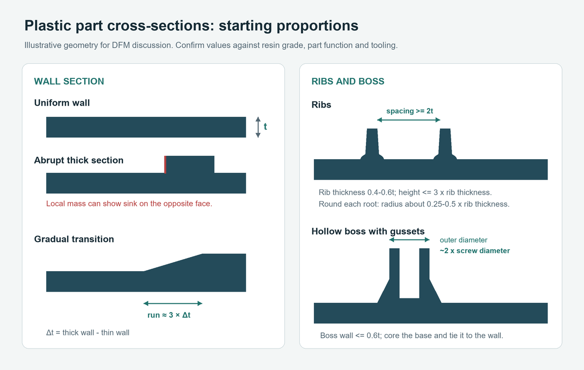
t means nominal wall thickness; Δt is the thick wall minus the thin wall. The transition run is about 3Δt. All proportions are starting points for a project-specific DFM review.
For a closer look at choosing the nominal wall, see injection molding wall thickness.
Holes, snap fits and threads
Holes close to an edge can leave too little plastic between the hole and the outside face. Deep blind holes can need slender core pins. Mark which holes locate the assembly, take a fastener or only clear a wire. For a snap fit, show how far the hook must flex and how it will leave the mold. For a thread, decide whether your volume and service needs justify an insert or a more complex tool.
For first-pass hole spacing, measure the clear plastic from a hole edge to the nearest outside edge or neighboring hole. Leave at least twice the nominal wall thickness or one hole diameter, whichever is larger. If you use center-to-center dimensions for two equal holes, add one diameter to that clear gap. Start a blind hole near two diameters deep and ask your mold maker about core support before going deeper. If your snap hook cannot release in the main pull direction (draw direction), compare a part change with a side action and its cost. For threads, compare a molded-in or post-installed insert with an unscrewing mold against torque, volume and maintenance needs. Your load and resin may call for more plastic around a hole.
Illustrative enclosure example
You can follow the review through this fictional enclosure. It is not a KTM customer project.
Imagine you are designing a small plastic enclosure with a visible outer face, four screw bosses, a mating edge and a side opening for a connector. You provide the assembly load, screw or insert choice, cosmetic limit and connector envelope. Your mold maker checks whether a boss leaves excess mass behind the visible face, whether the ribs and bosses can release in the pull direction, and whether the side opening changes the parting line or needs a slide.
You might move a boss away from the visible face, taper its wall connection and mark the mating edge for inspection. That boss move can change your gate options and fit at the same time. Show the choice and its remaining risks on one drawing revision before steel is cut.
The same tradeoffs show up on real parts at KTM. PA6 cable ties are hard to fill and prone to flash, complex PP automotive parts can show sink marks, clear PMMA lamp parts show weld lines, and structurally complex parts can deform.
Review pull direction, draft, texture and undercuts
Mark a likely pull direction on your model, then identify which surfaces belong on each side of the parting line. This reveals faces that may trap the tool and surfaces that need clearance to release.
For a first draft review, give a smooth face 1-2° of draft per side, light texture about 3°, and heavy texture 5° or more. Start rib and boss sidewalls at no less than 0.5°. A deeper draw, rougher texture or difficult ejection may need more draft. Check the actual texture and draw depth before you freeze the angle; a shallow polished wall and a deep textured wall will not release the same way.
Mark texture, polish, grain and coating expectations on your drawing or finish specification. Also show where an ejector mark or parting line can appear. A cosmetic face with a deep grain may need a different draft or split from a smooth reference face.
KTM commonly uses SPI A1 or A2 polish, VDI 21 to 36 texture and Mold-Tech MT-11010. Put the required finish on your drawing before setting draft.
An undercut may block a straight pull. For the side opening in the example, ask your mold maker to quote a part change and a side action side by side. Compare cost, maintenance, timing and the effect on your visible face before you choose. KTM's injection mold design and build page explains the tooling route; your drawing still needs the accepted option.
Review gate access, weld lines and appearance
On your model, mark where a gate witness is acceptable and where it is not. Show cosmetic faces, sealing surfaces, hand-contact areas, optical or fluid surfaces, and places where a visible flow mark would fail your requirement. Mark weld-line-sensitive features too, such as a loaded snap hook, a seal path or a narrow opening.
Mark an acceptable noncosmetic gate zone and any loaded or sealing feature that must avoid a weld line. Your mold maker may move the gate after checking flow length, wall changes, venting and appearance. Ask to see the proposed gate and likely weld-line zones on your model before approving the tool layout. Once you approve that layout, KTM's injection molding process guide follows the production stages that come next.
Specify fit and acceptance before tooling
Mark the dimensions that control your part's function: datums, mating edges, hole positions, sealing surfaces and assembly clearances. Distinguish critical dimensions from reference dimensions, and name the inspection method when it affects acceptance. Send the mating model or a clear envelope; your mold maker cannot judge a fit from an isolated part alone.
Use ISO 20457 as a general reference for molded-plastic tolerances and acceptance conditions, then call out the dimensions that control your assembly. Your molded dimension depends on resin, shrinkage, cooling and process settings as well as the cut tool. For a tighter fit, state the datum, temperature or conditioning state, measurement method and sample size.
KTM's routine tolerance is ±0.05 mm. We review tighter dimensions feature by feature because what a mold can hold also depends on part size, resin and geometry. KTM does not take parts where most dimensions need ±0.005 mm ultra-precision.
Before you inspect first shots, agree on the drawing revision, resin, cosmetic zones, fit checks and any load or leak test your part needs. If a sample misses one point, decide who can approve a deviation and whether another tool or part change is required. This prevents a sample review from turning into an argument about a requirement that never appeared on the drawing.
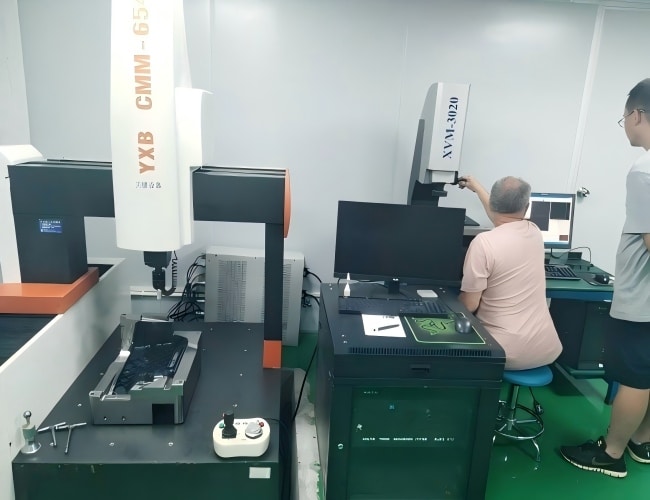
Within 2 days after T1 (the first trial), KTM ships 5 to 10 samples with a trial video and report. A dimension report follows; KTM uses the CMM where your drawing requires it. If your post-trial design change requires mold work, KTM prices the modification by the change.
What KTM looks for when you send a drawing
When you send a drawing to KTM, we look at wall changes, pull direction, possible gate zones and dimensions you need checked. Your project lead contacts you within 24 hours; an engineer evaluates the job. A mature design is usually quoted in 1 to 3 days, depending on size and complexity. If your design is not ready to quote, you get feedback. On customer drawings, KTM most often sees undercuts, too little draft, uneven wall thickness and structures that cannot release from the mold. KTM has in-house mold design, CNC machining and CMM inspection in Dongguan, and runs about 40 injection molding machines from 90T to 400T. Send mating geometry and acceptance criteria; machine capacity alone cannot validate your boss, seal or snap fit.
Use a pre-tooling DFM decision matrix
Use the matrix below to keep your model review and open decisions on one page. Ask which checks your mold maker will perform for this particular project.
| Design issue | Your input | Mold-maker review | Agreed decision |
|---|---|---|---|
| Resin and use conditions | Grade or performance needs, load, heat, chemicals, volume | Whether the assumed resin is compatible with the geometry and process route | Material assumption, alternatives and owner for approval |
| Wall sections, transitions and reinforcement | Functional loads, visible faces, boss, rib and fastener purpose | Local mass, transitions, flow and cooling risks; access for release and inspection | CAD revision or accepted risk with the affected zone named |
| Pull direction and draft | Preferred part orientation, finish, ejector-mark limits | Release surfaces, draw depth, texture and likely ejection approach | Pull direction, surfaces needing change and finish limits |
| Undercuts and parting line | Side openings, hooks, internal features and appearance boundaries | Straight-pull feasibility, parting line options and any required side action | Redesign, mechanism or accepted tooling consequence |
| Gate and appearance | Gate-mark zones, cosmetic faces, permitted weld-line areas | Flow path, gate access, venting and visibility risk | Gate zone, restricted zones and acceptance condition |
| Critical dimensions and fit | Datums, mating parts, critical dimensions and inspection method | Capability of the proposed design and measurement approach under the stated assumptions | Critical features, drawing revision and inspection record |
| Samples and acceptance | Functional test, cosmetic standard, material and sample revision | Whether the proposed checks expose the identified design risks | Sample approval criteria and deviation process |
For your enclosure, the boss behind a visible face touches both the wall and fit rows. The connector opening touches fit and the parting line. Agree on one coordinated CAD revision so a fix in one row does not create a new problem in another.
Prepare a reviewable RFQ and tooling handoff package
Send your mold maker a package that can be reviewed without reconstructing your project from scattered messages:
- 3D CAD with units, coordinate orientation and revision identifier.
- 2D drawing with datums, critical and reference dimensions, material or performance requirements and finish notes.
- Expected volume, launch assumptions and any family or variant relationship.
- Mating-part models, load cases, sealing details or connector envelopes that affect the fit.
- Marked cosmetic faces, gate-mark limits, texture or polish requirements and permitted parting or ejector marks.
- Sample acceptance checks, inspection conditions and the person authorized to approve a design change.
If you do not know a value yet, mark it open and name who will decide. Label your drawing, CAD, review comments and matrix with the same revision. Otherwise your mold maker may use review comments that refer to an older model.
Send a STEP model and 2D drawing with critical dimensions, plus your expected resin and volume if known. The model shows wall sections and pull direction a screenshot can hide. Check KTM's custom injection molding page for production fit, then send your drawings for review.
KTM's free DFM report checks whether your part can be molded and whether its structure is reasonable, including undercuts that block release. KTM provides the detailed mold DFM after the tooling order; it covers ejector positions, sink, filling and gate location. Mold flow analysis is charged and provided when you request it or when the structure is complex. Your project lead replies within 24 hours; mature designs are usually quoted in 1 to 3 days, depending on size and complexity.
Final pre-tooling checklist
Before you approve the next stage, confirm that:
- You have stated the part's function, environment, volume and resin assumption.
- You have reviewed wall transitions, ribs, bosses and heavy sections, with an owner for open changes.
- You have a proposed pull direction, draft, finish, parting line and undercut resolution.
- You have marked the gate, weld-line, venting and cosmetic zones that matter.
- You have identified critical dimensions, datums, mating parts and inspection conditions.
- You have written sample acceptance and deviation handling against a drawing revision.
- Your CAD, drawing, review matrix and open items are ready for the pre-tooling review.
You can still change a wall, boss or opening cheaply before the tool is cut. Use the review to settle the choices that affect your fit, appearance, release and inspection, then authorize tooling from the agreed revision. Keep any unresolved risk visible on that revision.
Written by

Henry Zeng
You may also interested in:
Injection Molding Wall Thickness: Choose a Wall That Can Fill and Perform
Injection molding wall thickness should be thick enough for the selected resin to fill the geometry and for the part to perform, while avoiding unnecessary mass that can cool unevenly