Injection Molding Wall Thickness: Choose a Wall That Can Fill and Perform
September 29, 2026 by Henry Zeng
Injection molding wall thickness should be thick enough for the selected resin to fill the geometry and for the part to perform, while avoiding unnecessary mass that can cool unevenly or mark the opposite face. You choose the nominal wall for the actual part, resin grade and flow path. Gate and vent assumptions, structural load, appearance and critical dimensions also affect that choice. Review the thinnest and thickest sections before tooling.
This guide gives you a practical way to mark up a drawing or CAD model. It explains how to choose a nominal wall, find risky thin and thick areas, and decide which changes need a design review, analysis, a tool trial or inspection. For the broader sequence of material, draft, gate and tolerance decisions, use the pre-tooling DFM guide. Here, focus on the main wall and the heavy local features an average thickness can hide.
Start with the part’s job, not a thickness chart
Begin with what your part must do. Record the selected resin grade, or the mechanical, thermal, chemical and appearance requirements that will determine it. Add the proposed gate and longest expected flow path, expected volume, assembly loads, mating surfaces, sealing features, critical dimensions and cosmetic faces. A wall that works for a protected internal bracket may be unsuitable for a visible cover or a part exposed to impact. If the grade is undecided, mark that decision as open on the drawing. Give the grade designation and supplier data sheet when available.
Uneven wall thickness is one of the problems KTM sees most often on customer drawings, along with undercuts and too little draft. You can make those issues easier to find by cutting CAD sections through the longest flow path, a fastener boss, any thick rim and the most visible face. A single overall part thickness hides the places that deserve review.
Separate the nominal wall from local features. The nominal wall is the main section used to describe your part. Ribs, bosses, gussets, collars, steps and pads are local changes that can alter filling, packing and cooling. Mark them separately on the model so a review does not treat a thick boss as if it were the same as the main wall. If a rib root, screw seat or sealing land needs extra material, give that feature its own reason and acceptance check. Do not let it quietly redefine the nominal wall for the entire part.

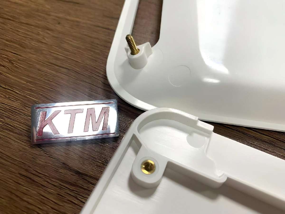
Hollow molded parts with internal threads and openings. Check the main wall separately from the material around these local features.
Keep the main walls as consistent as the function allows. Similar sections usually give you a more predictable flow and cooling path, although uniformity alone cannot prevent warpage or a surface defect. Gate location, venting, resin behavior, mold temperature, cooling balance and process settings still matter. Where a wall changes for a real load, fit or seal, show the change on the model and check what happens on both sides of it.
What sets the minimum wall thickness for injection molding?
Typical starting walls for common resin families are in the table below. If you propose a wall below the listed lower bound, arrange a flow review before treating that thin section as feasible. There is no single minimum wall thickness for injection molding that applies to every grade and part. Your lower bound depends on whether the selected grade can fill the longest and narrowest path under the proposed gate and process conditions, and whether that section can carry its load.
These are typical starting ranges for an early design discussion, not KTM specifications, guaranteed minimums or tool-shrinkage settings. They match the ranges in KTM’s published part-design guide. Use the selected resin grade’s data and your geometry before fixing a wall or mold allowance.
| Resin family | Typical starting wall (mm) | Illustrative mold-shrinkage range | What to check |
|---|---|---|---|
| ABS | 1.1-3.5 | 0.4-0.9% | Grade and visible-face requirements can change the choice. |
| PC | 1.0-3.8 | 0.5-0.7% | Check grade data and cooling near thick features. |
| PP | 0.9-3.8 | 1.0-2.5% | Grade, filler and part geometry affect shrinkage. |
| PA/nylon | 0.8-2.9 | 0.7-1.8% for PA66 | Moisture condition and grade need separate review. |
The shrinkage column is a screening aid. It does not tell you the tool allowance for a chosen grade. For a glass-filled grade, compare shrinkage along and across the flow direction separately; fiber orientation can affect fit at a remote mating feature. If you change materials later, reopen both the wall and dimensional review.
Then test the proposed minimum against four questions:
- How far must the melt travel? A remote thin section may be harder to fill than a short section of the same thickness. Flow length, turns, openings, inserts and weld-line locations can change the risk.
- What grade is actually being specified? ABS, PC, PP and nylon families contain many grades with different flow, reinforcement, shrinkage, moisture sensitivity and temperature requirements. A resin family name is not a complete process specification.
- Where will the material enter and where can air escape? Gate position and venting can change the filling path. A supplier chart can screen an early concept, but it cannot replace a grade-specific review.
- What strength or stiffness is needed? A section that fills may still be too flexible, too brittle or too weak around a fastener or mating feature.
Map your thinnest regions against the proposed flow path, predicted weld lines and critical loads. A short thin area near the gate is a different question from a thin end of fill after several turns. Mark each location on a section view instead of asking a supplier for one universal minimum. If a thin region is necessary, record what has to be checked through a flow review, a tool trial or sample inspection. The result may call for a wall change, a different gate or a different grade. You still need part-specific evidence that the section fills and performs.
What sets the practical upper wall?
A practical maximum wall thickness cannot be chosen from one number. A thick section creates a local cooling and packing problem. Material at the center can remain hot longer than the surface, and the surrounding geometry may shrink differently. A heavy section can contribute to sink on the opposite cosmetic face, internal void risk, longer cooling, added part weight or warpage. On real parts at KTM, complex PP automotive parts can show sink marks and structurally complex parts can deform.
That does not mean you must remove every thick section. A load path, sealing land or other functional feature may need local material. Identify why the mass is there, then compare it with a cored shape or reinforcement. If you keep it, mark the appearance and dimensional evidence you will need after a tool trial. A visible face opposite a boss deserves particular attention because the heavy junction can cool and shrink differently from the surrounding wall. Sink, void and distortion risks must be judged with the selected grade, geometry, gate and process assumptions.
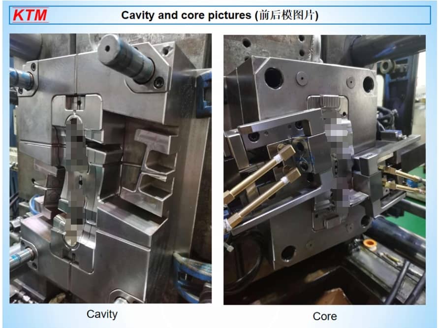
Cavity and core views from an existing tooling photo. Removing local mass from your part also requires a review of core support and tool access.
Keep the main wall consistent and transition deliberately
When your shape cannot be uniform, avoid an abrupt step where possible. Melt may favor a thicker, lower-resistance path while flow into an adjacent thin section slows and cools. That hesitation can leave the thin section incompletely filled; the outcome also depends on the resin grade, gate and process settings. A sudden change can concentrate mass on one side of a cosmetic face. Core out excess material, use a rib or gusset to carry load, and taper the change over a useful distance. Check the transition in section views that follow the likely flow path, since a smooth-looking outside surface can hide an abrupt change inside.
One Autodesk DFM handout gives a starting transition run of approximately 3Δt, where Δt is the difference between the thick and thin sections. For example, a change from 2 mm to 3 mm gives Δt = 1 mm and an initial run of about 3 mm. This is a starting geometry check, not a universal taper requirement. A larger step, long flow path, visible face or tight dimensional requirement may need a longer transition or another solution. Keep the calculation beside the drawing section that uses it so your reviewer knows which two walls were compared.
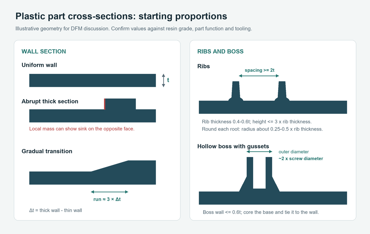
At general corners, start the inside radius at least 0.5 times the nominal wall thickness and make the outside radius the inside radius plus the wall thickness. That keeps the section closer to uniform around the turn. A corner near a loaded snap, a visible face or a long flow path still needs its own check. If that radius conflicts with a mating surface or tool access, show the constraint rather than hiding a sharp section change. Geometry analysis can locate thin and thick regions, but its result depends on the model and material inputs. You still need a part-specific review.
Reinforce without creating a solid mass
If your part needs stiffness, compare a cored shape, a rib, a gusset or a hollow boss with a solid block. A rib can stiffen the wall without adding the mass of a solid pad, but its root can still mark the opposite face. Put a rib or boss close to a visible face only after you have checked that junction. Check the selected resin, load, sink risk, ejection and tool access rather than copying proportions from a different part.
For a first rib layout, use these typical starting values from KTM’s published part-design guide: make rib thickness about 40-60% of the adjoining nominal wall, keep rib height no more than about three times its own thickness, and leave at least two wall thicknesses between adjacent ribs. Start the root fillet at 0.25-0.5 times rib thickness. These proportions give you a layout to review, not a guarantee against sink or breakage. A heavily loaded rib may need a different section or load path; a glass-filled grade may change how you assess flow, shrinkage and strength.
For a screw boss, a typical starting outside diameter is about twice the screw diameter, with the boss wall no more than 60% of the nominal wall thickness. Core out the base and connect the boss to a sidewall with gussets where the load path allows. Then review the actual screw or insert, boss height, core support, draft and assembly load together. A larger screw or a heavier load may call for a different boss, fastening method or support arrangement. Do not thicken the boss wall by default: the extra mass may sit directly behind the face you want to protect.
The defects KTM handles most are sink marks, flash, weld lines and warpage. The usual first moves are adjusting cooling time and building custom fixtures. Which response fits your part depends on the defect and its cause. Agree on a check that will show whether the change worked.

Molded tool-handle shell with internal ribs. This photo illustrates feature layout; it does not establish a suitable wall thickness for another part.
A hypothetical housing decision
The following housing is hypothetical. It illustrates decisions to review; it is not a KTM customer case or a validated production design.
Imagine you are designing a small tool housing with a visible outer face, an internal screw boss, one remote corner that must fill, and a mating rim with a critical fit. The resin grade, gate and loads are still open, so the example does not assign a wall dimension. Use it to connect each local feature to a decision and a way to check that decision:
- Boss behind the visible face: Start by asking whether a hollow boss with ribs or gussets can carry the fastener load without leaving a heavy junction behind the face. Mark the cosmetic side, the screw or insert choice and the proposed load check. The mold review can then examine sink risk, core support, ejection and the gate. On trial parts, look at both the face and the fastener function.
- Remote thin corner: This corner is far from the proposed gate. Show its flow path and vent options, then compare a local wall change with a different gate or grade. Flow analysis can help you choose which gate or wall change to test, but the samples must actually fill and meet the corner’s strength requirement. Record a weld-line concern if flows are likely to rejoin near the feature.
- Step from a stiff rim to the main wall: The rim needs stiffness, yet a solid step can create extra mass. Try a cored section or a gradual transition, including the 3Δt starting check where it fits. Put the transition, cooling concern and visible face on the same section drawing. Inspect the rim’s fit and any sink or distortion on the trial part.
- Critical mating edge: Define the datum, allowable fit and measurement method on your drawing. The selected grade’s shrinkage and the rim geometry must be reviewed together. If a fastening hole sits near the edge, a typical first-pass rule from the part-design guide is to leave clear plastic of at least twice the nominal wall thickness or one hole diameter, whichever is larger. That is an edge-to-edge clearance. For two equal holes dimensioned center to center, add one hole diameter to the clear gap. Confirm tool support and the actual mating fit on samples.
Mark the nominal wall, local mass, assumed flow path, cosmetic zones and critical dimensions on the model. Ask what would make each option fail: an unfilled corner, a mark behind the boss, a distorted rim or a fit that cannot be measured consistently. Agree on the validation plan before toolmaking, then use trial parts and inspection to close the remaining risks.
Pre-tooling wall-thickness handoff
Before you request a detailed review, prepare one drawing package that lets the reviewer connect each wall decision to a feature. If you need the full sequence from part design through tooling and production, see KTM’s injection molding process guide. For this wall review, prepare:
- the current CAD revision and a 2D drawing, with the revision identifier visible on both;
- the selected resin grade, or performance requirements if the grade is still open;
- a map of nominal, thin and thick sections, with local ribs, bosses and rims marked separately;
- the proposed gate or gate question, the longest flow path and remote features that may be difficult to fill;
- cosmetic zones, mating surfaces, sealing features and critical dimensions;
- assembly loads, fastener or insert requirements and expected volume;
- the proposed acceptance checks for appearance, fit and dimensions, including which sample features you will measure; and
- any questions about gate, venting, cooling, ejection or geometry changes.
KTM’s free DFM report checks whether your part can be molded and whether its structure is reasonable, for example undercuts that block release. Ejector positions, sink, filling and gate location are covered in the detailed mold DFM, which KTM provides after the tooling order. Mold flow analysis is done when you ask for it or when the structure is complex, and it is charged. You get a first reply within 24 hours.
Label the open decisions on your latest drawing. The grade may be fixed while the gate is still open, or the mating rim may be fixed while you can still core the boss. With those constraints visible, the reviewer can address the current design. Agree on the expected trial evidence before you treat a nominal wall, a thin corner or a cosmetic face as resolved.
For tooling scope, see KTM’s injection mold design and build page. If you also need to decide how the part will be produced, review custom injection molding. When your CAD revision, resin requirements and appearance limits are ready, send them through the contact page and ask for a review of the part’s wall and local features.
Written by

Henry Zeng
You may also interested in:

Plastic Part Design for Injection Molding: A Pre-Tooling DFM Guide
Review wall sections, draft, undercuts, gate zones, critical dimensions and sample acceptance before releasing an injection mold. Includes an illustrative enclosure and a DFM decision matrix.